[0016]The placement of the
receiver module in the bony region is semi-permanent thus minimizes
insertion frictions in the bony region, known to be extremely sensitive to touch and pressure. The
receiver module being extremely small and separate from the rest of the device allows for improved fit, manipulation,
visualization and navigation into and out of the ear canal. The receiver module is not encumbered by the presence of large components associated with an integrated hearing device. Similarly, the main module is smaller by excluding a receiver
assembly, thus easier to insert and manipulate into and out of the ear canal.
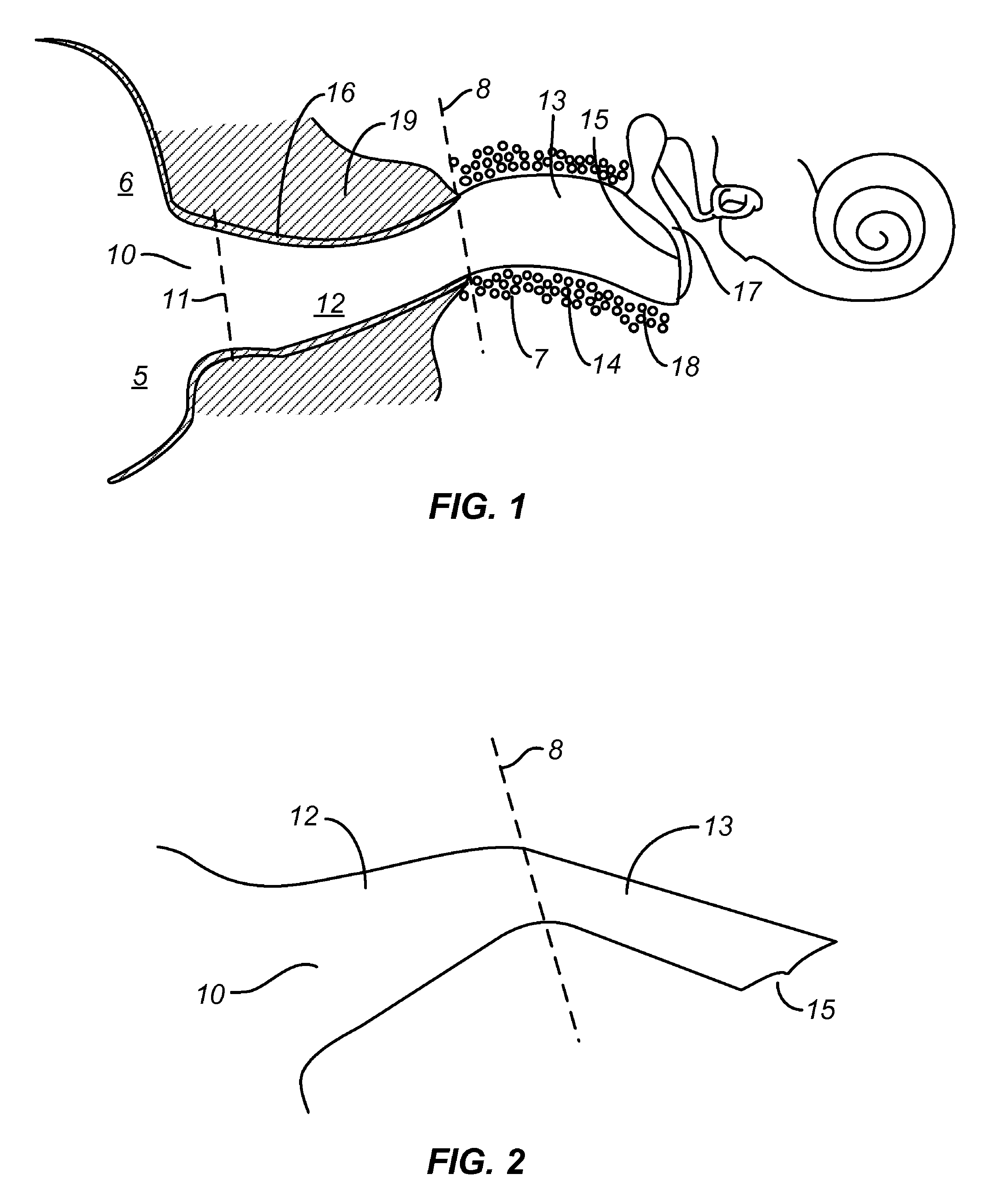
[0017]The receiver module is placed in proximity to the tympanic membrane resulting in superior sound and energy efficiency. The main module comprises a
microphone, a battery, a sound processor /
amplifier (
electronic circuit), and in the preferred embodiment an
inductive coupling coil for transmitting audio signals wirelessly to the receiver module. The receiver module remains immobile during its semi-permanent wear in the ear canal. The immobility of the receiver module allows for rapid acclimation of the sensitive bony region to the receiver module as a
foreign object. In contrast, the main module is positioned in the cartilaginous region, which is robust and far less sensitive to frequent touch and motion of the device including from mandibular movements. When the main module is removed, the receiver module remains in the ear canal with its acclimated
skin undisturbed.
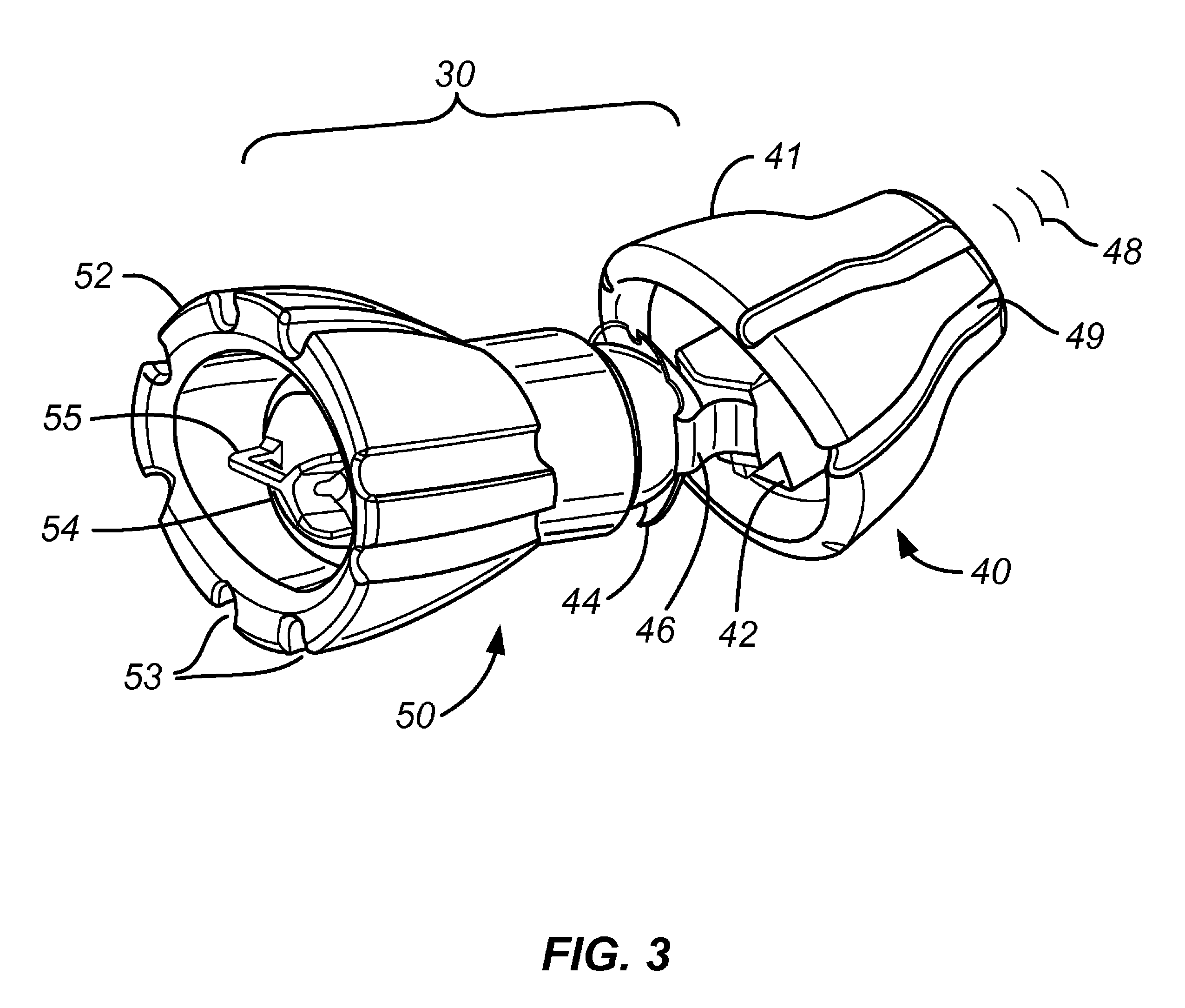
[0018]The main module and the receiver module are electromechanically isolated, either by an air gap or by the incidental contact of the
coupling elements. At least one
coupling element, if connecting, must be flexibly connected to provide
vibration isolation to control feedback. Vibration-caused feedback is well known in
hearing aid design and particularly for
CICs, thus they are limited in their application to less severe hearing impairments. The present invention eliminates such vibration
coupling and also prevents the transfer of motion from the main module to the receiver module (for example due to jaw movements, sleeping on the ear, yawning, etc.), thus eliminating
skin rubbing and
irritation in the bony region where the receiver module resides.
[0019]The main module is placed preferably entirely in the ear canal with the lateral end at or past its aperture, beyond the concha region. In other embodiments, the main module may extend to the concha region for improved access for persons of limited dexterity. The receiver module being in the bony region is less prone to
contamination from physiologic debris (i.e, cerumen) present in the cartilaginous area thus can be worn for
extended wear exceeding 4 months. By eliminating frequent insertions, cumulative scooping of earwax is minimized. Earwax
contamination of receiver sound port is a common problem that plagues canal hearing devices, leading to exceptionally high repair and return rates.
[0020]Deep placement of the invented device allows for invisible and hassle-free wear, features highly sought after by
hearing impaired individuals. Placement of the
microphone inside the ear canal or within the concha area provides natural sound pick-up by taking
advantage of natural ear
acoustics. The combined effect of receiver placement near the
eardrum and microphone placement in the ear leads to significantly improved
sound quality including less
distortion, less apparent
noise, less
wind noise, improved
frequency response, and improved
speech perception by preserving localization of sound, particularly in noisy conditions.
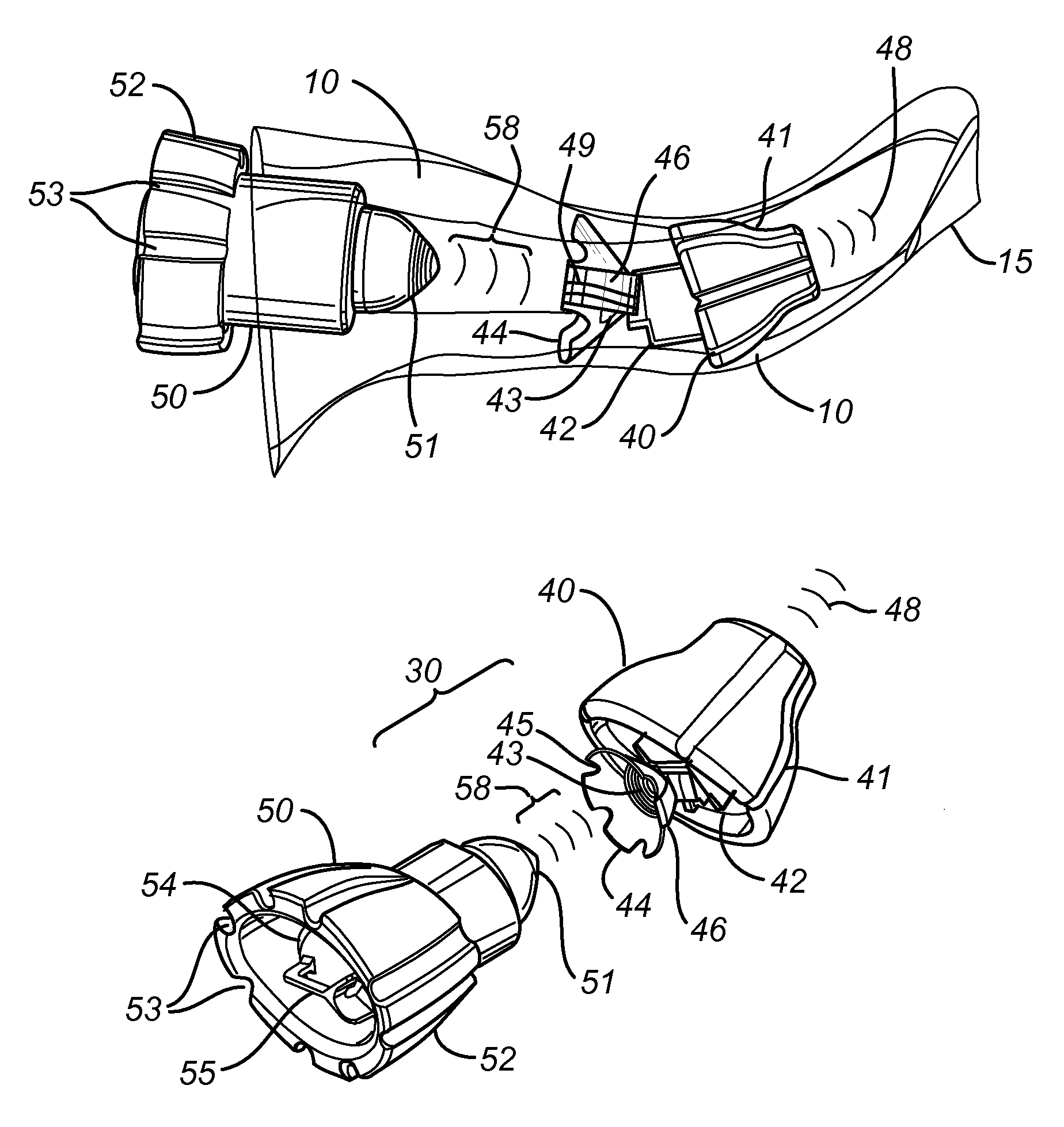
[0024]In one aspect, the present invention provides a modular hearing device for inconspicuous wear in the ear canal, comprising: a speaker module for placement medially in the ear canal in the bony region and in proximity to the eardrum, said speaker module comprises a speaker
assembly for delivering amplified sound to the tympanic membrane, a skin contacting
retainer concentrically positioned over said speaker
assembly for retaining said receiver assembly entirely in said ear canal, and a receive coil for
wireless reception of
electromagnetic signal representing audio signals; and a main module laterally positioned primarily in the cartilaginous region of the ear canal, comprising a microphone, a power source and a transmit coil for
wireless transmission of said
electromagnetic signal representing
audio signal to said receive coil within said speaker module, said main module is separately removable from the ear canal while said speaker module remains therein when said main module is removed; and wherein said speaker module is activatable by the presence of said main module when placed inside the ear canal in proximity thereto.

