Insulator material and method for manufacturing thereof

a technology of insulation material and manufacturing method, which is applied in the direction of cellulosic plastic layered products, liquid handling, and closures using stoppers, etc., can solve the problems of increasing the radial acceleration of the components, the relationship of wall thickness and gas filled volume, and the total breakdown of the insulation material. to achieve the effect of keeping the breakdown strength of the insulator material constan

Inactive Publication Date: 2013-01-01
KONINK PHILIPS ELECTRONICS NV
View PDF8 Cites 5 Cited by
  • Summary
  • Abstract
  • Description
  • Claims
  • Application Information

AI Technical Summary

Benefits of technology

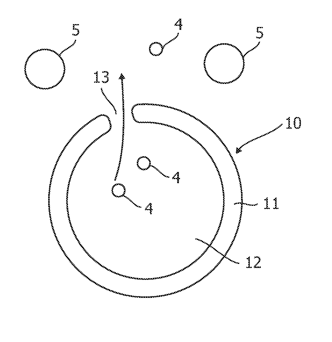
[0010]Using an alveole having a porous wall structure, having pores with a diameter that gas molecules like air, N2, CO2, SO2 can pass through, and being small enough that polymer chains of a typical thermo setting material like, for example, epoxy resin and their hardener components cannot pass through, these alveoles may be used as a filler within an insulation material. It is possible to evacuate the alveoles so that the gas within the alveoles may escape from the cavity of the alveole, and at the same time to avoid the entering of polymer molecules to maintain the vacuum in the alveole.
[0071]It may be seen as the gist of the present invention to provide a high voltage insulating material which can be optimised in terms of weight, dielectric strength and mechanical strength in a relatively simple manner by utilising the high breakdown voltage at very low pressures according to the Paschen law.

Problems solved by technology

In particular applications, there is a need for an insulator material, which is of a light weight, in particular when exposed to a high acceleration, for example in computer tomography devices, in which the high voltage parts are rotating in a high speed, which results in a high radial acceleration of the components.
From a certain energy over a certain time onwards, this electrical erosion process caused by partial discharges destroys first the wall of the, e.g. glass of the hollow micro-spheres, depending on the wall thickness and next the surrounding epoxy resin matrix resulting in a total breakdown of the insulation material.
Reducing the diameter means that the relation of the wall thickness to the gas filled volume becomes worse and by that the weight of the total hybrid material comes up.

Method used


Image

  • Insulator material and method for manufacturing thereof
  • Insulator material and method for manufacturing thereof
  • Insulator material and method for manufacturing thereof

Examples


Embodiment Construction

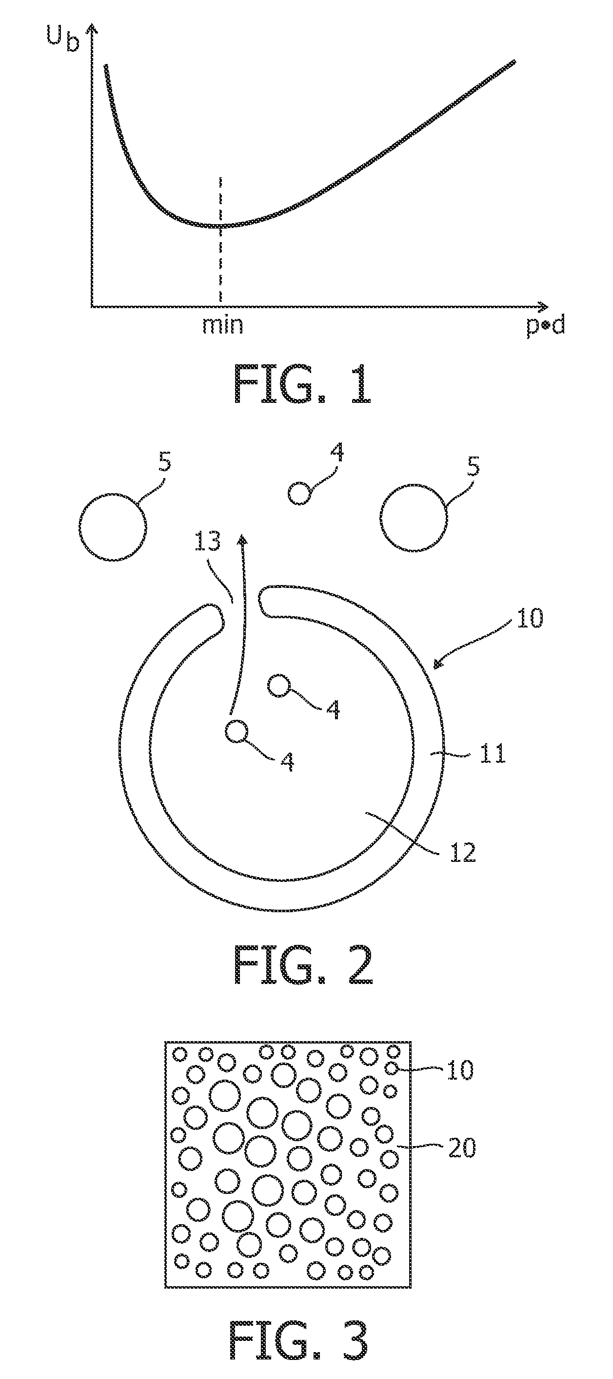
[0084]FIG. 1 illustrates the Paschen curve according to the Paschen law. The Paschen law illustrates the relation between a breakdown voltage Ub and the product of the pressure p and the distance d. According to the Paschen law, the breakdown voltage Ub can be expressed as follows:

[0085]Ub=c⁢⁢2⁢pdln⁡(c⁢⁢1⁢pd)-ln⁢⁢ln⁢⁢1 / γ

[0086]Ub is the breakdown voltage, p is the pressure within the geometry, d is the distance between the two electrodes which can be considered as the diameter of, for example, the alveole, γ (gamma) is the third Townsend coefficient representing a material constant, typical values thereof are γ=0.01 to 0.1; c1 and c2 are material constants representing the material of the gas and the electrodes. According to the Paschen law depicted in FIG. 1, the breakdown voltage depends on the gas, wherein for air the minimum is at about 0.4 Pa×m. For larger pd Ub increases almost linear since the free length of path decreases at higher pressures leading to an increased breakdown ...


PUM

PropertyMeasurementUnit
diameteraaaaaaaaaa
pressureaaaaaaaaaa
pressureaaaaaaaaaa

Abstract

Vacuum filled hollow alveoles embedded in an insulation material in order to arrive at a light weight insulation material using the high breakdown voltage of evacuated cavities, i.e. alveoles at a vacuum lower than the minimum of the Paschen law. Pressurized hollow alveoles embedded in an insulation material in order to arrive at a light weight insulation material using the high breakdown voltage of pressurized cavities, i.e. alveoles at a pressure higher than the minimum of the Paschen law.

Description

FIELD OF THE INVENTION[0001]The present invention relates to an insulator material, an insulator device, a method for manufacturing of the insulator material and the insulator device and to an alveole for being embedded into the insulator material, and in particular to an insulator material and an insulator device as well as a method for manufacturing thereof, which allows to provide an improved light weight insulator material and insulator device.BACKGROUND OF THE INVENTION[0002]In particular applications, there is a need for an insulator material, which is of a light weight, in particular when exposed to a high acceleration, for example in computer tomography devices, in which the high voltage parts are rotating in a high speed, which results in a high radial acceleration of the components. Therefore, there is a need for a light weight material in order to reduce the moved masses in order to reduce the forces due to a high radial acceleration. From EP 1 176 856, it is known that f...

Claims


Application Information

Patent Timeline
Patent Type & Authority Patents(United States)
IPC IPC(8): B29D22/00
CPCH01B3/006Y10T428/1376Y10T428/2982
Inventor NEGLE, HANS
Owner KONINK PHILIPS ELECTRONICS NV
Why Eureka
Try Eureka