
Method and system for continuous wave interference suppression in pulsed signal processing

a pulsed signal and pulsed wave interference technology, applied in the field of pulsed signal processing methods and systems, can solve the problems of limited compute power, unfavorable known systems employing cw interference suppression for small embedded tactical applications, etc., and achieve the effect of improving the system and method, reducing the number of computations, and less computational resources

Active Publication Date: 2013-01-01
RAYTHEON CO
View PDF6 Cites 2 Cited by
  • Summary
  • Abstract
  • Description
  • Claims
  • Application Information

AI Technical Summary

Benefits of technology

This patent describes a system and method for eliminating interference in pulsed signal processing. The system includes a front-end, A / D converter, data store, and suppressor module. The system uses a reduction technique called G-based discrete Fourier transform (G-DFT) to process the waveform and detect desired data pulses. The system is faster and more efficient than existing methods and can be embedded in smaller systems. Additionally, the system helps alleviate problems with false detections and distortion. Overall, this system provides a faster and more accurate way to process pulsed signals.

Problems solved by technology

Known systems employing CW interference suppression are just not feasible for small embedded tactical applications where compute power is limited due to having reduced computational resources on hand.
Many current CW interference suppression systems simply live with these false detections and distortion problems and commit additional computational resources to remove such after detection.

Method used


Image

  • Method and system for continuous wave interference suppression in pulsed signal processing
  • Method and system for continuous wave interference suppression in pulsed signal processing
  • Method and system for continuous wave interference suppression in pulsed signal processing

Examples


Embodiment Construction

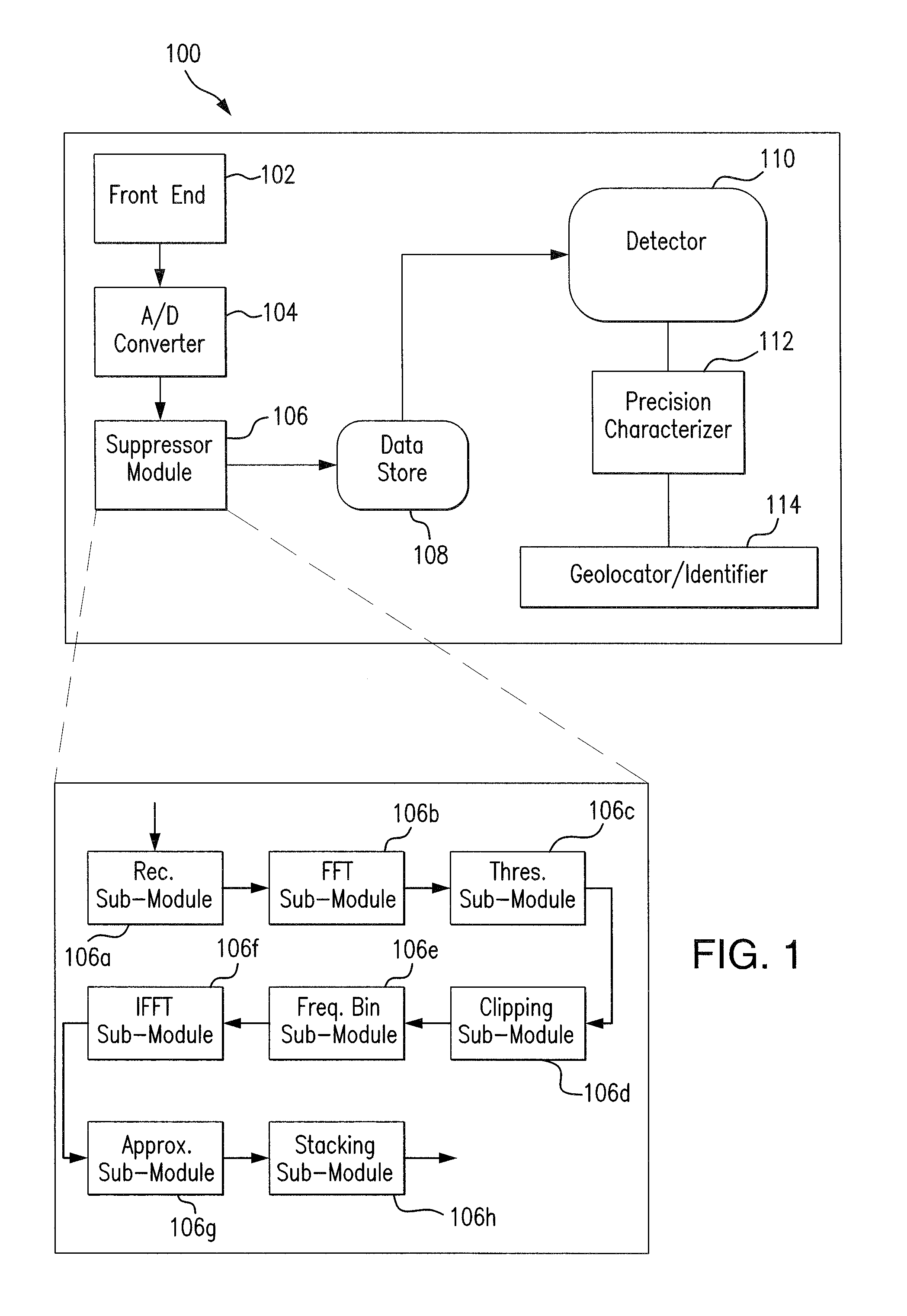
[0023]Referring to FIG. 1, a block diagram illustrating the various components of one embodiment of a system 100 within which a method for continuous wave (CW) interference suppression in pulsed signal processing may be implemented. In one embodiment, system 100 may be comprised of a front-end 102, an A / D converter 104, a suppressor module 106, a data store 108, a detector 110, a precision characterizer 112 and a geolocator / identifier 114. In this particular embodiment, front-end 102 is electrically coupled to, or otherwise in communication with, the A / D converter 104. Front-end 102 is comprised generally of standard software and hardware electronics commonly used in the industry for transmitting and receiving electronic signals. Alternatively, in another embodiment, front-end 102 may be equally comprised entirely of software residing in the memory associated with a stand-alone processing system or equally implemented in any of such other form as is generally known and practiced in ...


PUM


Abstract

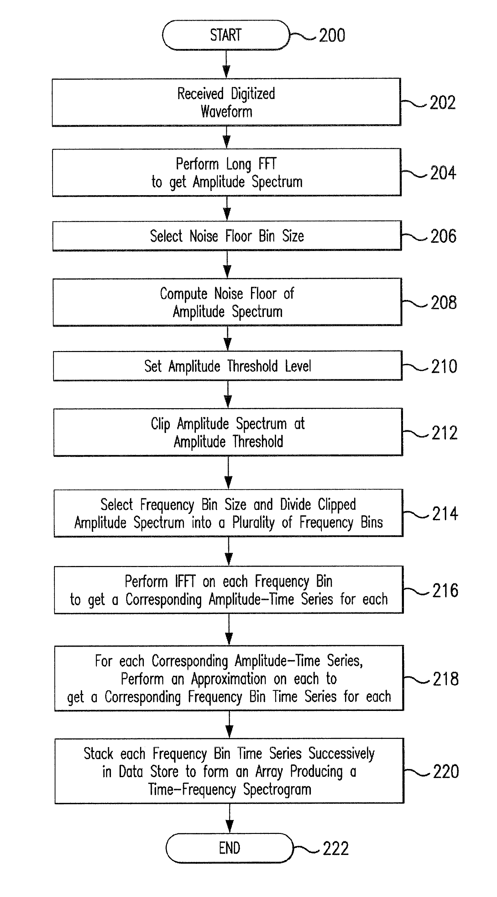
A System and Method for CW interference suppression in pulsed signal processing having a front-end, an A / D converter, a data store, and a suppressor module coupled to both the A / D converter and the data store. The front-end is operable to receive a waveform and communicate such to the A / D converter to digitize for processing by the suppressor module. The suppressor module being operable to further process the digitized waveform by way of applying a FFT to obtain a corresponding amplitude spectrum of the digitized waveform, clipping the amplitude spectrum to obtain a clipped amplitude spectrum, performing successive piece-wise IFFTs on the positive frequency points of the clipped amplitude spectrum to obtain multiple amplitude-time series, each having a frequency value assigned, and then stacking such amplitude-time series successively in the data store to form a time-frequency spectrogram array to thereby facilitate suppression of interference signals and detection of data pulses.

Description

TECHNICAL FIELD OF THE DISCLOSURE[0001]This disclosure relates generally to a pulsed signal processing method and system. More particularly, this disclosure relates to a method and system for suppressing continuous wave interference signals in pulsed signal processing.BACKGROUND OF THE DISCLOSURE[0002]Interference signals are a major problem in the field of electronic communication signals and, in particular, with radar systems. Coming up with new and improved processes and solutions to sort out the unwanted interference signals from the desired signals is a continuing pursuit in the signal processing industry. Continuous Wave (CW) interference is one form of interference signal that is typically encountered in a number of Radio Frequency (RF) bands where radar systems operate. The presence of heavy CW interference in these RF bands is created in large part from commercial radio, TV, and cellular telephone transmissions.[0003]In general, CW interference signals introduce a large ave...

Claims


Application Information

Patent Timeline
Patent Type & Authority Patents(United States)
IPC IPC(8): G01S13/00G01S13/58G01S13/08
CPCG01S7/2923G01S7/023
Inventor GOODMAN, VERNON R
Owner RAYTHEON CO
Learn More