
Radio frequency antenna for heating devices

a radio frequency antenna and heating device technology, applied in the direction of electric/magnetic/electromagnetic heating, instruments, electric signalling details, etc., can solve the problems of loss of necessary rf communication between the tag and the reader, the inability to place the rfid reader antenna in a heatable portion of the object, and the inability to maintain rf communication with the handle-mounted rfid reader antenna, etc., to achieve the effect of small penetration

Active Publication Date: 2013-01-08
TSI TECH LLC
View PDF18 Cites 12 Cited by
  • Summary
  • Abstract
  • Description
  • Claims
  • Application Information

AI Technical Summary

Benefits of technology

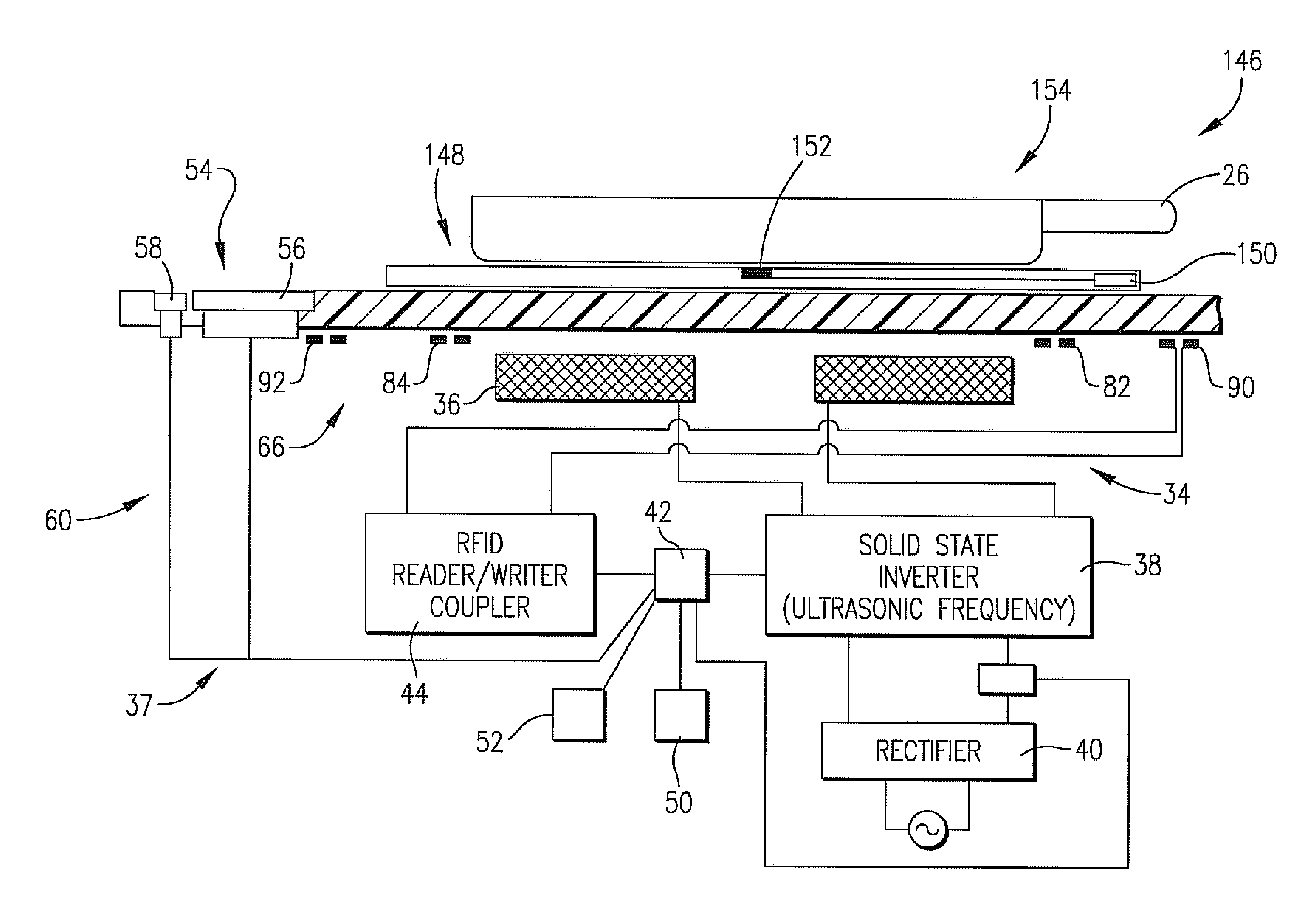
The invention is an antenna that is particularly useful for heating objects using induction. It is designed to be used with components such as induction hobs that generate a magnetic field to heat objects. The antenna has multiple loops, which allows it to interrogate RFID tags associated with the heated objects and receive information from them. This is advantageous because the loops have very little penetration area for the magnetic field, which minimizes the noise that is induced by the alternating magnetic field. This results in a higher signal-to-noise ratio compared to a single loop antenna that surrounds the induction hob and experiences severe induced noise.

Problems solved by technology

Hence, it is often impractical to place the RFID tag or other transponder in a heatable portion of the object such as the center symmetry position.
However, this patent teaches that the RFID reader antenna can only maintain RF communication with the handle-mounted RFID tag through a limited angular rotation of the vessel.
Consequently, where the RFID tag is handle-mounted, the vessel must be maintained in a relatively small range of angular positions, else the necessary RF communication between the tag and reader will be lost.
This presents a significant problem to the user, i.e., casual or even professional users may accidentally move the vessel handle out of the range of the RFID antenna during food preparation.
Moreover, many users wish to place vessel handles in various different orientations for ease of food preparation or to ensure that a given handle is not inadvertently contacted, resulting in spillage.
However, this system is inherently very complex, still only allows for RF communications over a limited portion of the periphery of the hob, and does not provide a full answer to the problem.
No known prior art describes any structure or means which provides a RF antenna forming a part of a heating device for use with cookware, servingware, or other heatable objects equipped with peripheral-mounted RF transponders, wherein the object being heated can be rotated through substantially 360° and / or radially displaced without loss of RF communication between the transponder and heating device.
Accordingly, there is a real and unsatisfied need in the art for an improved antenna useful with a variety of heating devices and which establishes a substantially continuous RF communication zone outboard of and substantially surrounding the hob(s) of the heating device, thereby allowing a user to rotate an object being heated having a peripheral RF transponder to virtually any desired angular position without communication loss.

Method used


Image

  • Radio frequency antenna for heating devices
  • Radio frequency antenna for heating devices
  • Radio frequency antenna for heating devices

Examples


Embodiment Construction

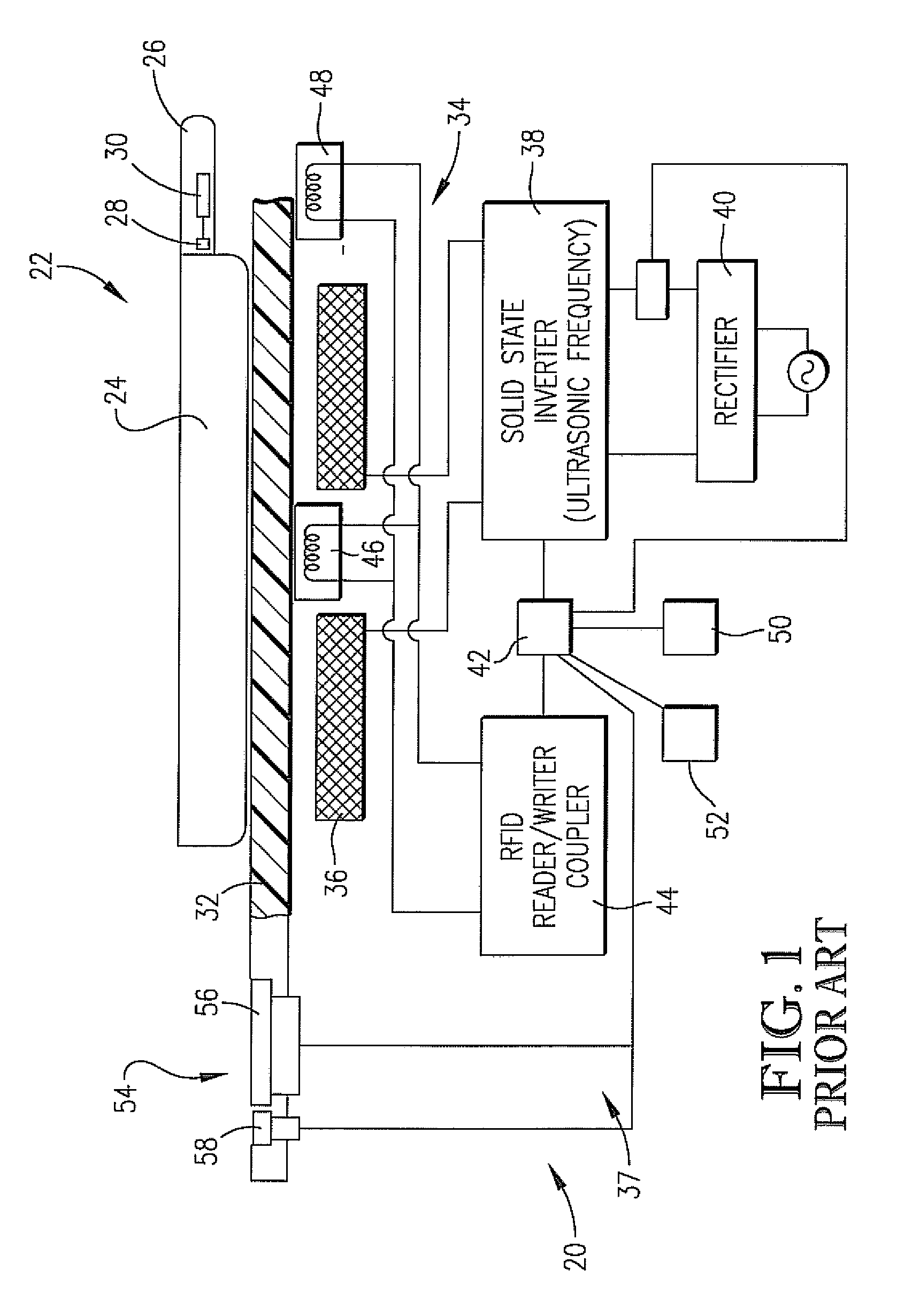
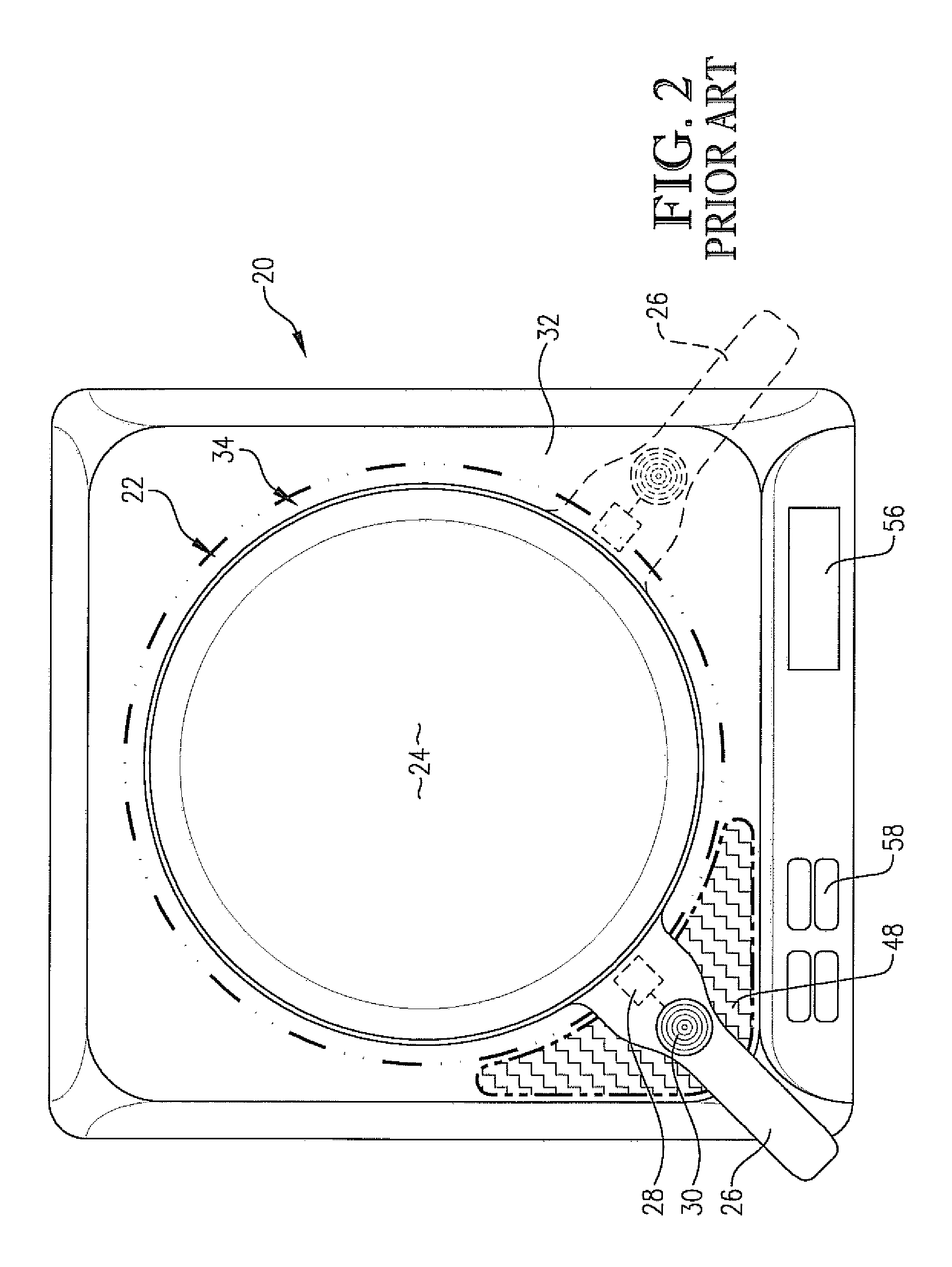
[0029]Referring first to FIGS. 1 and 2, a prior art induction heating apparatus 20 and associated heatable cooking vessel 22 are illustrated. This apparatus is of the type described in U.S. Pat. No. 6,953,919 incorporated by reference herein in its entirety.

[0030]In general, these Figures depict an exemplary RFID-equipped cooking vessel 22 in the form of a pan or skillet having a food-holding section 24 and elongated handle 26. The handle 26 includes a resistant temperature sensing device 28 in thermal connection with the section 24, and an electrically coupled RFID tag 30.

[0031]The heating apparatus 20 includes an upper support 32 adapted to support vessel 22 as shown. The apparatus 20 also includes one or more hobs 34 having a work coil 36 and associated ultrasonic frequency inverter 38 and rectifier 40. As illustrated, the vessel 22 is positioned directly above the hob 34 and work coil 36. The overall control circuitry 37 associated with the apparatus 20 includes a microprocessor...


PUM


Abstract

An improved antenna assembly (66) designed to maintain RF communication between an object (22, 64, 148) to be heated, and a heating assembly (20, 60) such as an induction heater having a hob (34) equipped with an induction work coil (36). The antenna assembly (66) provides substantially continuous RF communication about the entirety of the hob (34), so that the object (22, 64, 148) can be rotated through substantially 360° , or displaced radially, without loss of RF communication. The preferred antenna assembly (66) includes an antenna (67) mounted upon a substrate (68) and presenting a plurality of continuous, conductive antenna loops (70, 72) oriented to cooperatively and substantially surround the hob (34).

Description

BACKGROUND OF THE INVENTION[0001]1. Field of the Invention[0002]The present invention is broadly concerned with improved RF antenna assemblies used as a part of an induction or other type of heating apparatus in order to establish and maintain RF communication between the heating apparatus and an object being heated having a peripheral-mounted RF transponder. More particularly, it is concerned with such antenna assemblies, as well as overall heating systems and combinations thereof including heatable objects, making use of the improved RF antenna assemblies. The preferred RF antenna assemblies comprise multiple antenna loops cooperatively defining a substantially continuous RF communication zone outboard of a cooking hob.[0003]2. Description of the Prior Art[0004]Several prior art induction heating systems have been developed which use RF communications between a transmitter / receiver forming a part of the induction heater, and a radio frequency transponder (e.g., a RFID tag) associa...

Claims


Application Information

Patent Timeline
Patent Type & Authority Patents(United States)
IPC IPC(8): H05B6/12H05B6/08
CPCH05B6/062H05B2213/05
Inventor BUCHANAN, SHAWN M.
Owner TSI TECH LLC
Learn More