Pressure vessel for treating dentures

a pressure vessel and denture technology, applied in the field of denture treatment, can solve the problems of difficult to achieve the required sealing performance with standard, difficult to maintain intimate contact between the sealing gasket and the surface abutting the sealing gasket, and difficult to apply the force necessary to maintain an adequate seal, etc., to achieve the effect of reducing stress, improving the ease of manipulating the handle, and reducing the amount of dentur

Active Publication Date: 2013-01-15
BARHAM WILLIAM L
View PDF25 Cites 3 Cited by
  • Summary
  • Abstract
  • Description
  • Claims
  • Application Information

AI Technical Summary

Benefits of technology

[0009]A denture treating apparatus according to one embodiment of this invention and possessing characteristics sufficient to overcome the enumerated and other difficulties encountered in the development of this apparatus, includes a cover that can be mounted on a receptacle base to enclose a pressure containment chamber or cavity. The receptacle base forms the majority of this chamber, which has an open end at the top of the receptacle base so that the chamber can be filled with water or some other fluid. The receptacle base includes a receptacle base peripheral lip extending around the open end of the chamber. The cover can be secured to the receptacle base over the open end of the chamber, to close the chamber. The cover includes a cover peripheral lip opposed to the receptacle base peripheral lip when the receptacle base is secured to the open end of the chamber. A seal is positioned between the receptacle base peripheral lip and the cover peripheral lip. The cover can be rotated relative to the receptacle base to compress the seal to form a pressure tight chamber in which a denture can be treated or cleaned. The receptacle base comprises a one-piece molded member including a cylindrical outer wall and a bottom wall. The cylindrical outer wall is thicker in a section forming the receptacle base peripheral lip than in a section forming the bottom wall. The thin wall extends over the majority of the receptacle base and are easier to fabricate, but the thicker peripheral lip provides a surface, which will not excessively deform under pressure while in engagement with the seal. The cover can have also employ a relatively thick cover peripheral lip compressing the seal. A relatively thinner receptacle base bottom section can bow outward under pressure to show a user that an effective pressure is being developed within the gas tight chamber. Also a relatively thinner bottom section will relieve stress that would otherwise tend to deform the sealing rim.
[0010]A denture treating apparatus, that can be closed by a user who may not possess normal grip strength employs handles on the cover and the receptacle base. One handle is attached to the cover and engages the cover to twist the cover relative to the receptacle base to open and close the chamber. This handle is shiftable relative to the cover between multiple positions to improve the ease of manipulating the handles to close the cover. The cover handle imparts rotation in opposite directions to open and close the chamber.
[0011]The cover of this apparatus may also include a holder in which a denture treatment tablet may be mounted prior to introducing the tablet into water in the receptacle base chamber. In this way an effervescing tablet will only begin to emit gas as the cover encloses the chamber, and gas will not be lost before the chamber is closed. Effective pressure can then be more reliably developed by an inexperienced user.

Problems solved by technology

However, it has been found that the combination of the required sealing performance with standard, relatively inexpensive manufacturing methods is difficult to achieve.
Otherwise it would be difficult to maintain intimate contact between a sealing gasket and the surfaces abutting the sealing gasket.
Since most denture wearers are elderly, the pressure vessel needs to be configured so that it can be closed by users who may possess less than average strength and may find it difficult to apply the force necessary to maintain an adequate seal.
These requirements impose somewhat contradictory limitations of a denture treatment apparatus having the desired capabilities.

Method used


Image

  • Pressure vessel for treating dentures
  • Pressure vessel for treating dentures
  • Pressure vessel for treating dentures

Examples


Embodiment Construction

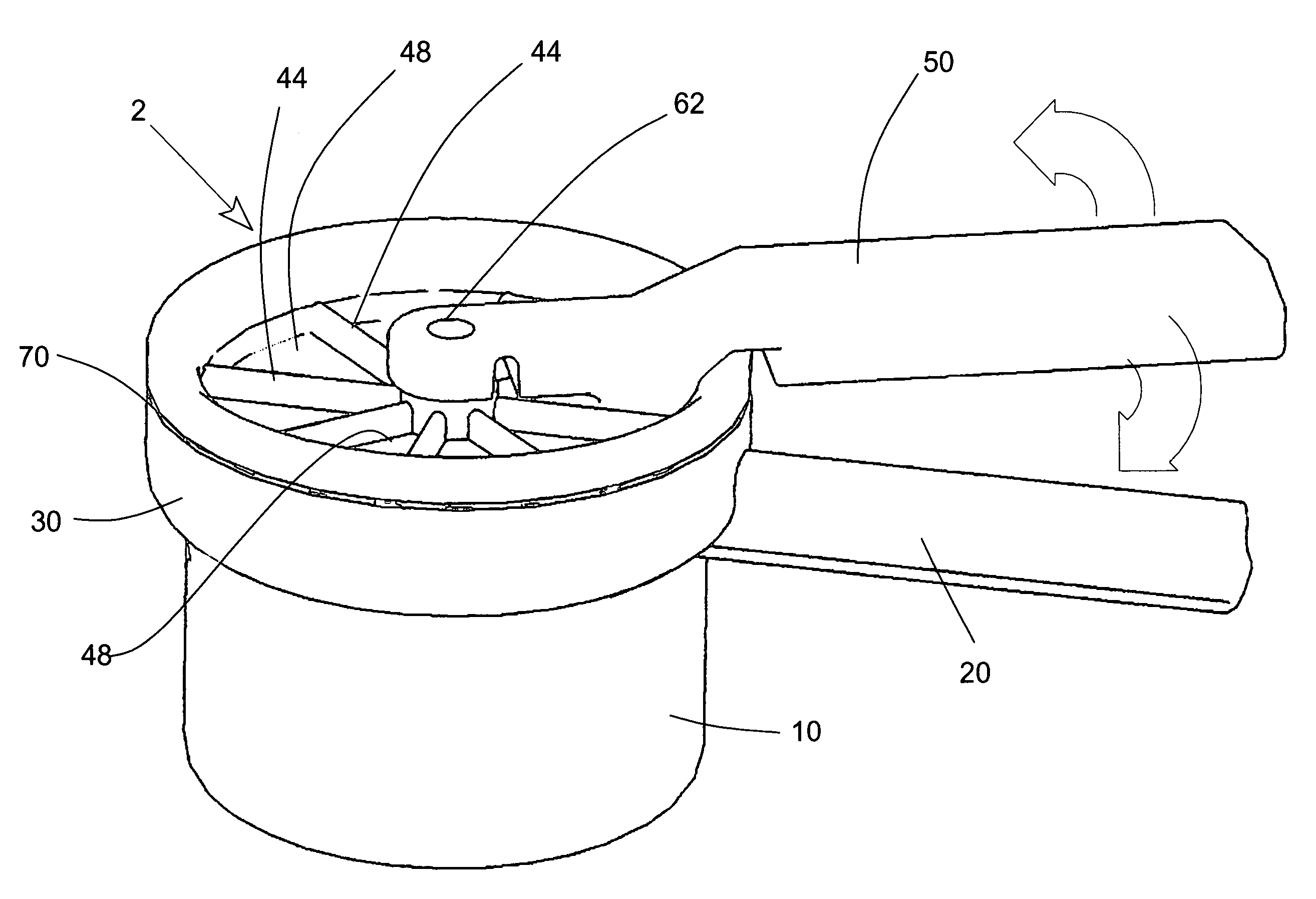
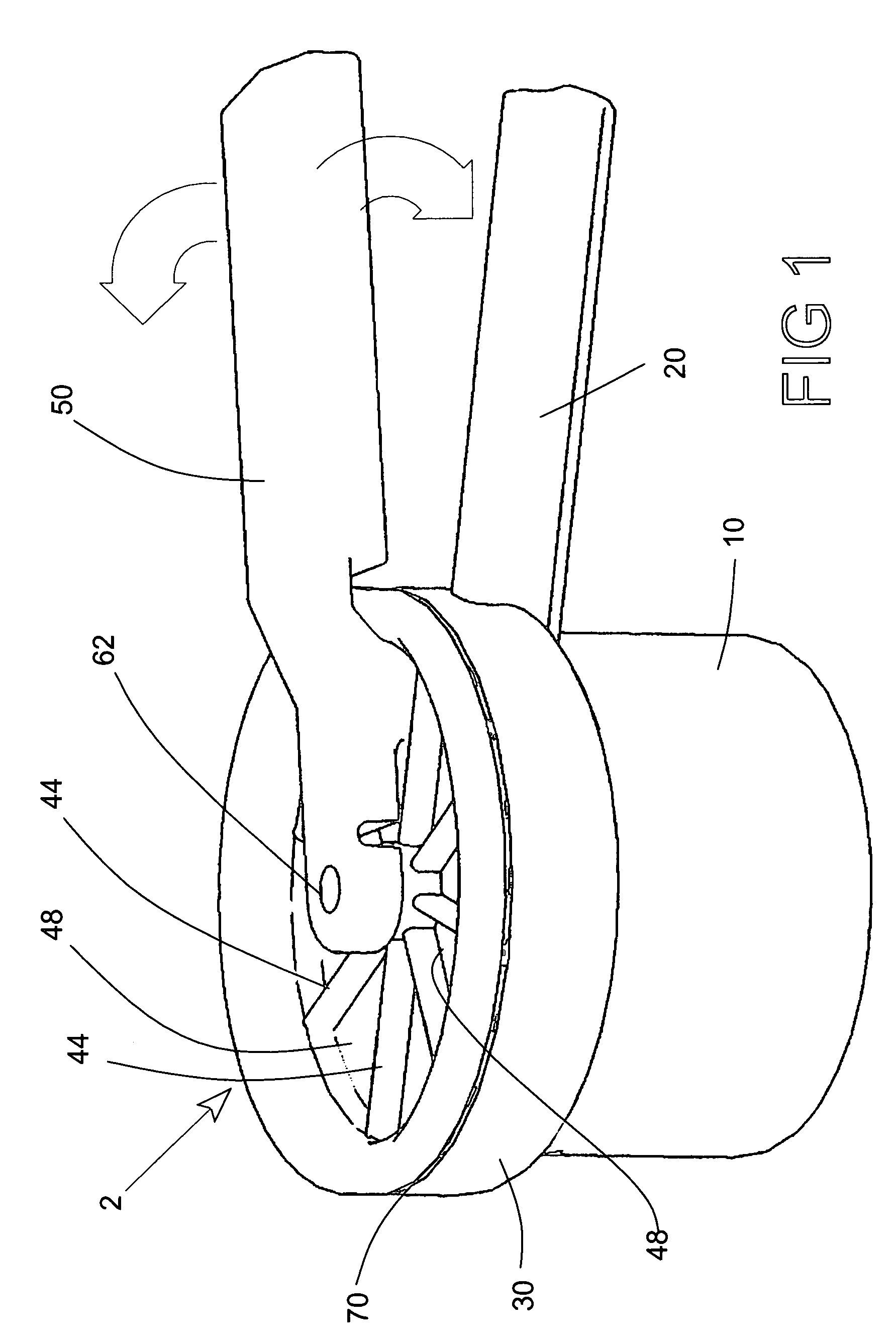
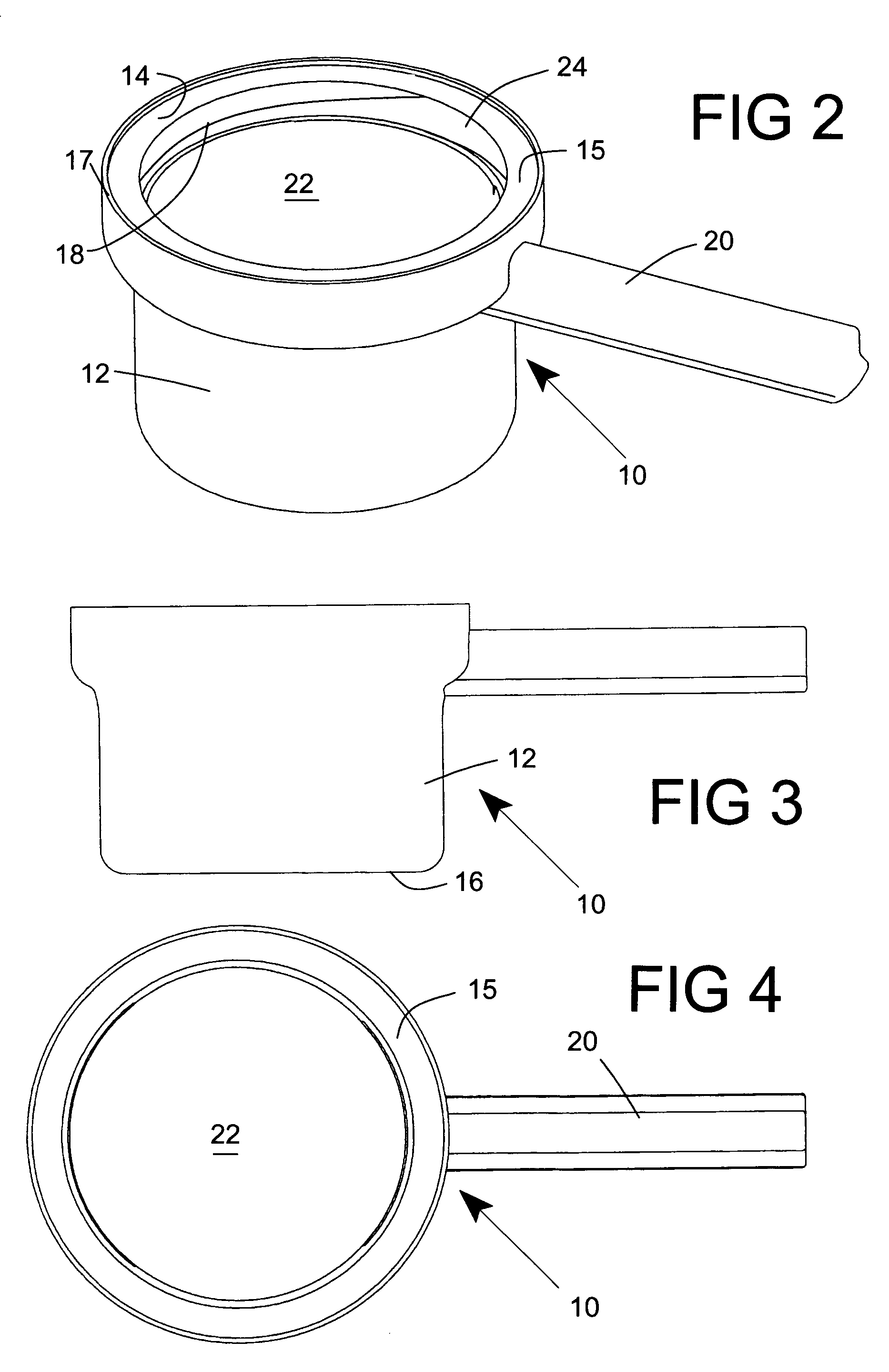
[0029]The denture treating apparatus 2 according to the preferred embodiment of this invention can be employed to treat dentures. Normally vessel 2 would be employed to clean a denture using any one of a number of commercially available standard denture cleaning tablets. This invention can be employed to improve the effectiveness of standard effervescent denture cleaning tablets including both cleaning and foaming agents. Conventional tablets, such as Efferdent denture cleaning tablets and Polident denture cleaning tablets could be employed. Efferdent is a trademark of Warner-Lambert and Polident is a trademark of Glaxo Smith Kline. Use of this pressure enhanced denture treatment apparatus 2 is not limited to use of these commercially available compositions. Other treatments, including cleaning, disinfecting, deodorizing, brightening, bleaching or other compositions could also be employed. For example, the treatment agent could include menthol or eucalyptus oil. Other treatment agen...


PUM


Abstract

A denture treating apparatus employs a receptacle base with a chamber closed by a rotatable cover. A denture and an effervescing denture treating composition, such as a denture cleaning tablet is place in water in the chamber. When the chamber is closed, the pressure created by the effervescing tablet causes the active ingredients to penetrate small spaces in the denture. A seal is compressed between relative thick peripheral lips on the cover and receptacle base. Thinner sections of the receptacle base can bow under pressure to show that pressure is building up. A shiftable handle on the cover makes it easier for a user to close the cover and compress the seal.

Description

BACKGROUND OF THE INVENTION[0001]1. Field of the Invention[0002]This invention is related to the treatment of dentures and especially to more effectively cleaning or deodorizing dentures. This invention is also directed to the removal of biolayers that can build up in confined spaces within a denture and to the capability of denture treatment compositions to wet or contact confined areas where these biolayers can be deposited.[0003]2. Description of the Prior Art[0004]Many methods and techniques have been suggested to facilitate cleaning and disinfecting dentures. Denture cleaning can be broadly defined as the reduction of a biolayer or biofilm and plaque containing bacteria, fungi and virus and pathogens or debris in general. Generally some method is employed to disrupt the plaque coating or biolayer and to soak the denture to allow chemical solutions to interface with denture surface and with porosities, micro-channels, fissures, cracks, fractures and spaces between teeth and the ...

Claims


Application Information

Patent Timeline
Patent Type & Authority Patents(United States)
IPC IPC(8): B01D1/18A61C17/00
CPCA61C17/036
Inventor BARHAM, WILLIAM L
Owner BARHAM WILLIAM L
Why Eureka
Try Eureka