Doherty amplifier with input network optimized for MMIC

a technology of input network and amplifier, which is applied in the direction of amplifier combination, rf amplifier, multiple-port network, etc., can solve the problems of power-dependent power split ratio, power-dependent phase shift of input network, and difficult implementation of high-quality power-divider in mmic, so as to reduce the performance of doherty amplifier, and reduce the negative effect of variable input impedan

Inactive Publication Date: 2013-01-15
OPTIS CIRCUIT TECH LLC
View PDF13 Cites 32 Cited by
  • Summary
  • Abstract
  • Description
  • Claims
  • Application Information

AI Technical Summary

Benefits of technology

[0010]For example, the phase difference between the inputs and the outputs of the main stage and of the peak stage may assume values of up to 30° as a function of the input and output power levels. A 30° phase mismatch between the input and output of the Doherty amplifier causes power losses of about 0.3 dB and a loss in efficiency of about 3%. Substantial phase differences occur especially during the peak stage becoming active (i.e., when it is being turned on). Also, the phase characteristic of the input network is more frequency dependent than that of the output low-pass C-L-C Doherty combiner, thus limiting the Doherty operational frequency bandwidth. This parameter can be improved up to some level in exchange for compromising the gain of the Doherty amplifier, by introduction of losses at the input of the Doherty amplifier, which make the dependence of the input phase shift on power and frequency less pronounced.
[0018]It is possible to reduce electrical memory effects by means of realizing low impedance and a smooth phase characteristic for the power supply networks of the amplifier (in other words: realizing a so-called wide band high-frequency video-decoupling). Traditionally, a network of an LC low-pass filter configuration is used for video-decoupling. A proper network of this kind is very difficult to design for wide-bandwidth applications owing to the appearance of parasitic parallel resonances that cannot be avoided. An ideal solution would be a network consisting of just a single L-C step, wherein L has a value close to zero and C has a value that approaches infinity. A practical solution, close to the ideal one, is a parallel inductance that is used as a matching component located close to drain or to the gate of the FET in the main stage or the peak stage. If this inductance is grounded through large capacitance, the node between the inductance L and capacitance C can be used for power supply of the device providing the smallest memory effects. Simulation indicates that in this way the value of inductance 116 can be dramatically decreased from 3.5 nH per 150 W device provided by the traditional solution, to just 0.2 nH for the same power device manufactured in LDMOS using the aforementioned practical solution.
[0021]Accordingly, the inventor now proposes an input power distribution network, which is suitable for an MMIC environment, and proposes a circuit as specified by claim 1. This approach now makes it possible to create a phase difference between the signal at the input node of the main device and the signal at the input node of the peak device that is largely independent of the frequency over the frequency band of interest. From another point of view, this approach enables to have the imaginary parts of the impedances in the input combiner at least partially compensate each other at the common input of the Doherty system over the frequency band, thus at least reducing frequency dependence.

Problems solved by technology

Implementation of a high-quality power-divider in MMIC is difficult, due to substrate losses and limited space available.
Without port isolation this causes a power-dependent phase shift of the input network, and also a power-dependent power split ratio.
As a result, a non-optimal output power combining occurs at the output of the Doherty system, that in turn causes a loss of back-off efficiency and / or of linearity and peak power capability.
This may seriously hamper the performance of the Doherty amplifier in the sense that such characteristics like efficiency, linearity and / or power capability, cannot be optimized individually without adversely affecting the other.
A 30° phase mismatch between the input and output of the Doherty amplifier causes power losses of about 0.3 dB and a loss in efficiency of about 3%.
Also, the phase characteristic of the input network is more frequency dependent than that of the output low-pass C-L-C Doherty combiner, thus limiting the Doherty operational frequency bandwidth.
This issue is especially important if the input network of the Doherty system does not provide isolation between the main and peak devices.

Method used


Image

  • Doherty amplifier with input network optimized for MMIC
  • Doherty amplifier with input network optimized for MMIC
  • Doherty amplifier with input network optimized for MMIC

Examples


Embodiment Construction

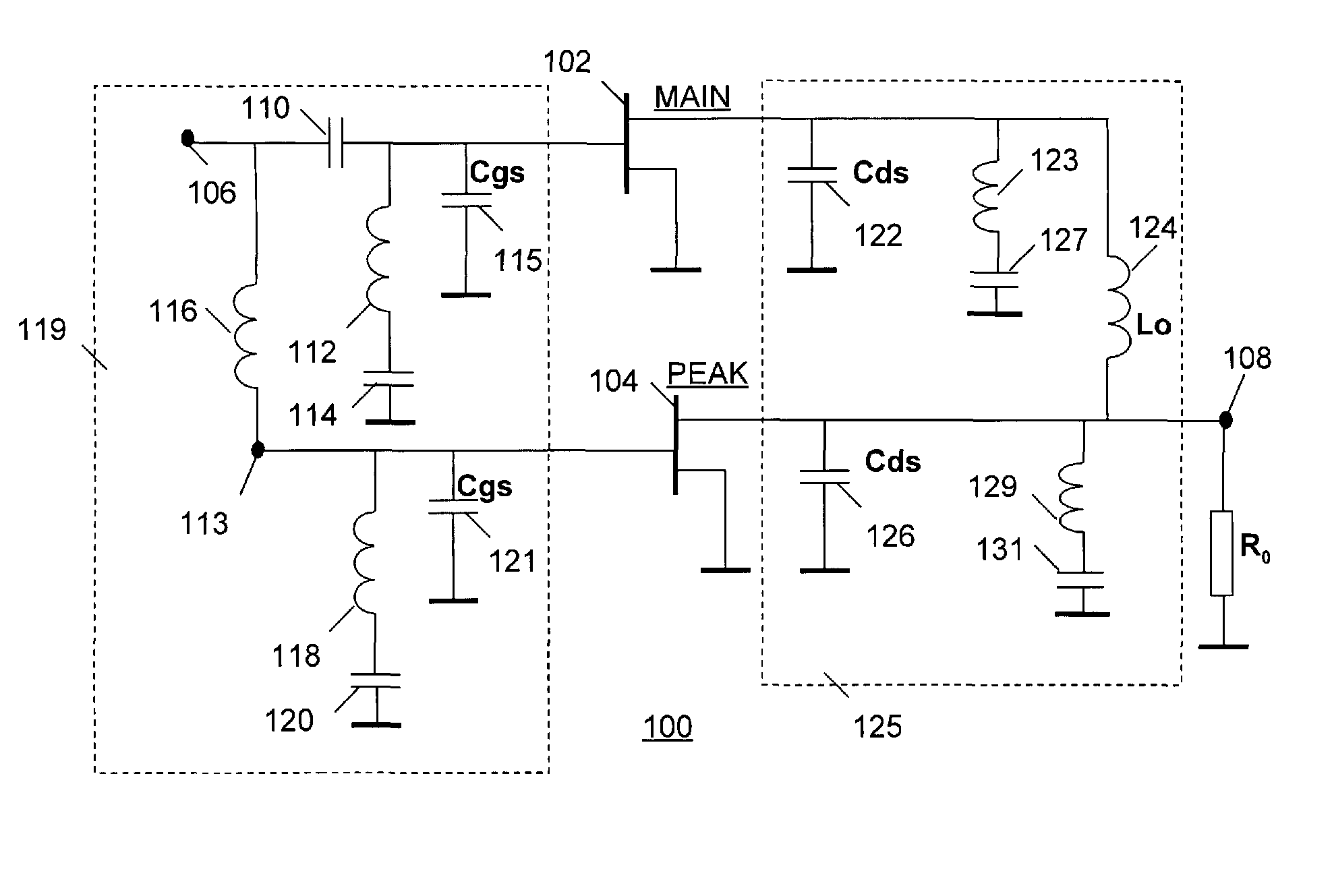
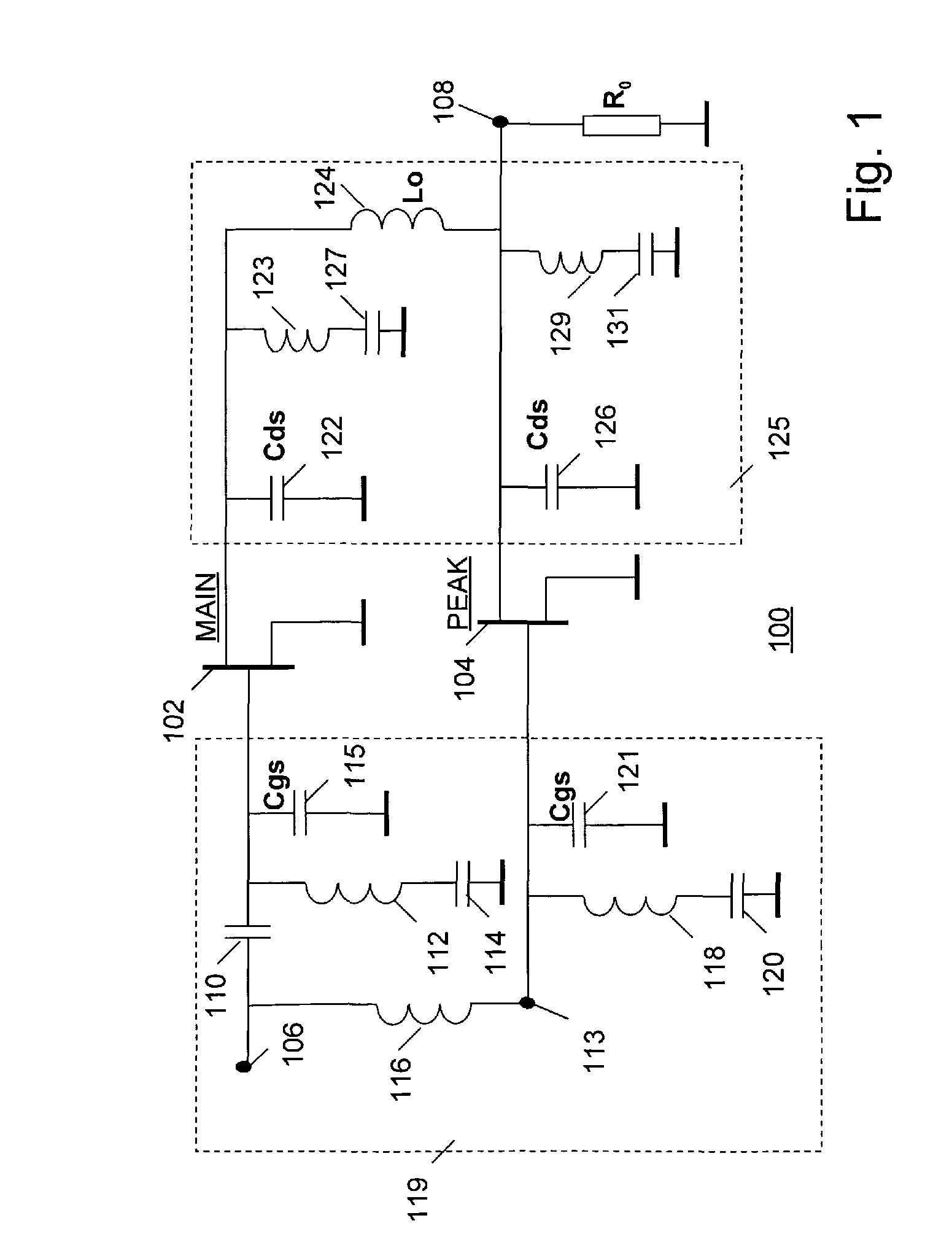
[0032]As known, a classical Doherty amplifier has two amplifying stages arranged in parallel and of the same power capability. The first one of the stages (main stage) operates in a class-AB amplifier mode and the second one (peak stage) operates in a class-C amplifier mode. These stages are separated at their inputs and at their outputs by 90° phase-shifting networks. The output phase-shifting network has a specific characteristic impedance Z0 which must be equal to the optimal load impedance RLm of the main stage. The input signal is split so as to drive the two amplifiers, and a summing network, known as an “impedance inverter” or a “Doherty combiner”, is operative to: a) combine the two output signals, b) to correct for phase differences between the two output signals, and c) to provide an inverted impedance at the output of the Doherty amplifier with respect to the impedance as seen from the output of the main stage.

[0033]In the embodiment of FIG. 1, the state of the art integr...


PUM


Abstract

In a Doherty amplifier (100), the amplifier's input is connected to a main device (102) via a first branch and to a peak device via a second branch. The first branch has a first frequency-dependent input impedance with a first real part and a first imaginary part. The second branch has a second frequency-dependent input impedance with a second real part and a second imaginary part. The first and second imaginary parts have opposite polarity. The first and 5 second imaginary parts have a same magnitude so as to compensate each other in the frequency band. The first imaginary part and the second imaginary part implement a first phase shift in the. first branch and a second phase shift in the second branch, respectively. The first and second phase shifts each have a magnitude of substantially 45 degrees substantially in the middle of the frequency band and are of opposite polarity. The phase difference of the 10 input signals to the main (102) and peak (104) devices stays largely constant over the frequency band.

Description

FIELD OF THE INVENTION[0001]The invention relates to an electronic circuit comprising a Doherty amplifier for use in a frequency band.BACKGROUND ART[0002]A classical Doherty amplifier has two amplifying devices arranged in parallel and of the same power capability. The first one of the devices (main stage) operates in a class-AB amplifier mode and the second one (peak stage) operates in a class-C amplifier mode. These devices are separated at their inputs and at their outputs by 90° phase-shifting networks. The output phase-shifting network has a specific characteristic impedance Z0 which must be equal to the optimal load impedance RLm of the main stage. The phase shifting output network is also known as an “impedance inverter” or a “Doherty combiner”. The Doherty combiner is operative to: a) combine the two output signals, b) to correct for phase differences between the two output signals, and c) to provide a load impedance to the output of the main stage that has at any moment in ...

Claims


Application Information

Patent Timeline
Patent Type & Authority Patents(United States)
IPC IPC(8): H03F3/68
CPCH03F1/0288H03F3/195H03H7/38H03F2200/222H03F2200/225H03F2200/451
Inventor BLEDNOV, IGOR
Owner OPTIS CIRCUIT TECH LLC
Why Eureka
Try Eureka