Receiver for optical transverse-mode-multiplexed signals

a transverse-mode multi-plexing and receiver technology, applied in multiplex communication, instruments, optical elements, etc., can solve the problem that the hardware for implementing optical mimo is not yet sufficiently developed

Active Publication Date: 2013-01-15
RPX CORP
View PDF34 Cites 23 Cited by
  • Summary
  • Abstract
  • Description
  • Claims
  • Application Information

AI Technical Summary

Problems solved by technology

However, the hardware for implementing optical MIMO is not yet sufficiently developed.

Method used


Image

  • Receiver for optical transverse-mode-multiplexed signals
  • Receiver for optical transverse-mode-multiplexed signals
  • Receiver for optical transverse-mode-multiplexed signals

Examples


Embodiment Construction

Optical Communication System

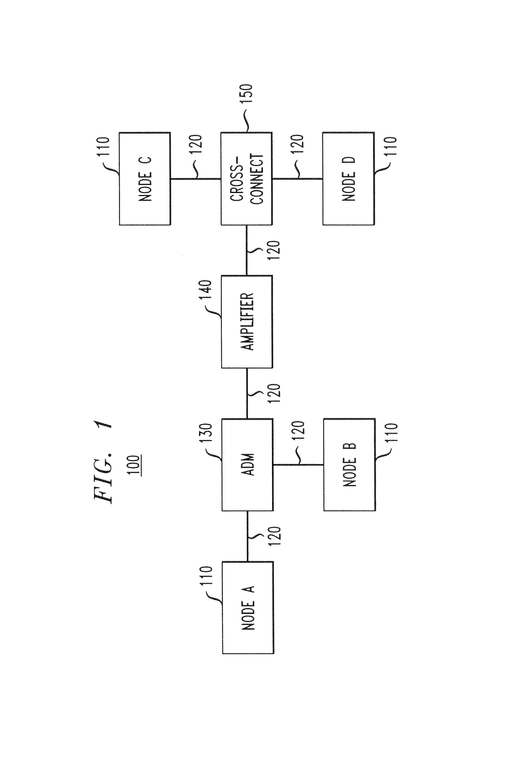
[0027]FIG. 1 shows a block diagram of an optical communication system 100, in which various embodiments of the invention can be practiced. System 100 has a plurality of communication nodes 110 interconnected via a network of optical communication links 120. System 100 further has an optical add / drop multiplexer (ADM) 130, an optical amplifier 140, and an optical cross-connect 150, all variously interposed between nodes 110.

[0028]Each node 110 has optical multiple-input multiple-output (MIMO) capabilities achieved through the use of transverse-mode multiplexing (TMM). Node 110 generally includes an optical transmitter and an optical receiver (neither is explicitly shown in FIG. 1) to enable two-way communications between various nodes of system 100. In addition to TMM multiplexing, an individual node 110 might also use wavelength-division multiplexing (WDM) and / or polarization multiplexing (PM), or both. Representative embodiments of an optical transmitter...


PUM


Abstract

A representative optical receiver of the invention receives an optical transverse-mode-multiplexed (TMM) signal through a multimode fiber that supports a plurality of transverse modes. The optical receiver has a plurality of optical detectors operatively coupled to a digital signal processor configured to process the TMM signal to determine its modal composition. Based on the determined modal composition, the optical receiver demodulates each of the independently modulated components of the TMM signal to recover the data encoded onto the TMM signal at the remote transmitter.

Description

CROSS-REFERENCE TO RELATED APPLICATIONS[0001]The subject matter of this application is related to that of U.S. Patent Application Publication No. 2010 / 0329671 which application publication is incorporated herein by reference in its entirety.BACKGROUND[0002]1. Field of the Invention[0003]The present invention relates to optical communication equipment and, more specifically but not exclusively, to the equipment that enables transverse-mode multiplexing (TMM) in optical communication systems.[0004]2. Description of the Related Art[0005]This section introduces aspects that may help facilitate a better understanding of the invention(s). Accordingly, the statements of this section are to be read in this light and are not to be understood as admissions about what is in the prior art or what is not in the prior art.[0006]Wireless communication systems with multiple-input multiple-output (MIMO) capabilities increase the overall transmission capacity by exploiting (instead of trying to mitig...

Claims


Application Information

Patent Timeline
Patent Type & Authority Patents(United States)
IPC IPC(8): H04B10/60
CPCH04B10/2581H04B10/60H04B10/611H04B10/613H04B10/614H04J14/002H04J14/04G02B6/34G02B6/2817H04J14/06H04J14/021H04B10/65
Inventor ESSIAMBRE, RENE'-JEANRYF, ROLANDWINZER, PETER J.
Owner RPX CORP
Why Eureka
Try Eureka