Thermally activated shutdown seals for rotatable shafts

a shutdown seal and rotating shaft technology, applied in the direction of machines/engines, liquid fuel engines, lighting and heating apparatus, etc., can solve the problems of limiting the available pressure, further wear, unstable and unpredictable, etc., and achieve the effect of improving the roundness of the annulus of the ring

Active Publication Date: 2013-01-22
WESTINGHOUSE ELECTRIC CORP
View PDF35 Cites 33 Cited by
  • Summary
  • Abstract
  • Description
  • Claims
  • Application Information

AI Technical Summary

Benefits of technology

[0012]Preferably, the shutdown seal also has a pliable polymer seal ring which is urged against the shaft by an increase in pressure in the housing when the split ring blocks the leakage of coolant through the annulus. In one further embodiment the roundness of the annulus of the ring is improved when the ring is restrained in the open position by thickening a radial portion of the ring's circumference approximately 180° from the split.

Problems solved by technology

), the reactor coolant pump seal experiences mixed flow (steam and water) which may be very unstable and unpredictable.
Even in this most extreme case where the No. 1 Seal does not provide any sealing, the shutdown seal can only provide this amount of differential pressure for approximately 12 seconds, after which it wears away to the point that it will release enough from the shaft to begin pressure-sharing—which limits the available pressure to cause further wear.
When the shutdown seal actuates on a rotating shaft, the damage is self-limited.
The amount of wear to which the shaft is limited is nearly undetectable via human touch.
Once the maximum wear has occurred, the shutdown seal no longer seals well enough to induce the polymer ring to constrict around the shaft.
With the No. 1 Seal regaining more and more of the differential pressure as the shutdown seal opens, lower and lower forces are present to cause the shutdown seal to wear.
Not only will the shutdown seal not be severely damaged or damage the No. 1 Seal when it inadvertently actuates, the shutdown seal is likely to seal if the shaft is stopped in a loss of all seal cooling event.
The response of the No. 1 Seal to the marked increase in temperature is to have its taper angles rollback which opens the seal and creates greater leakage.
Even when the entire polymer ring is worn away and the shaft is worn to its self-limited dimension, the shutdown seal still functions as a flow-limiting device in a loss of all seal cooling event.
Too large of a ring diameter is just as likely to leak as one too small.
Too large and the ends of the ring will abut and not allow the entire circumference to contact the sleeve.
Too small and there will be a gap between the ends through which flow can escape without generating sufficient differential pressure to reduce flow or induce the polymer ring to constrict.
First, it must not be so strong as to prevent the spacer of the retracting actuator to be pulled from between the ends of the split ring.
This typically leads to the polymer becoming more amorphous and the properties, especially the tensile and flexural properties, start to drop.
In other words, initially the increase in temperature reduces the mechanical properties of the PEEK, allowing it to constrict and begin to seal.

Method used


Image

  • Thermally activated shutdown seals for rotatable shafts
  • Thermally activated shutdown seals for rotatable shafts
  • Thermally activated shutdown seals for rotatable shafts

Examples


second embodiment

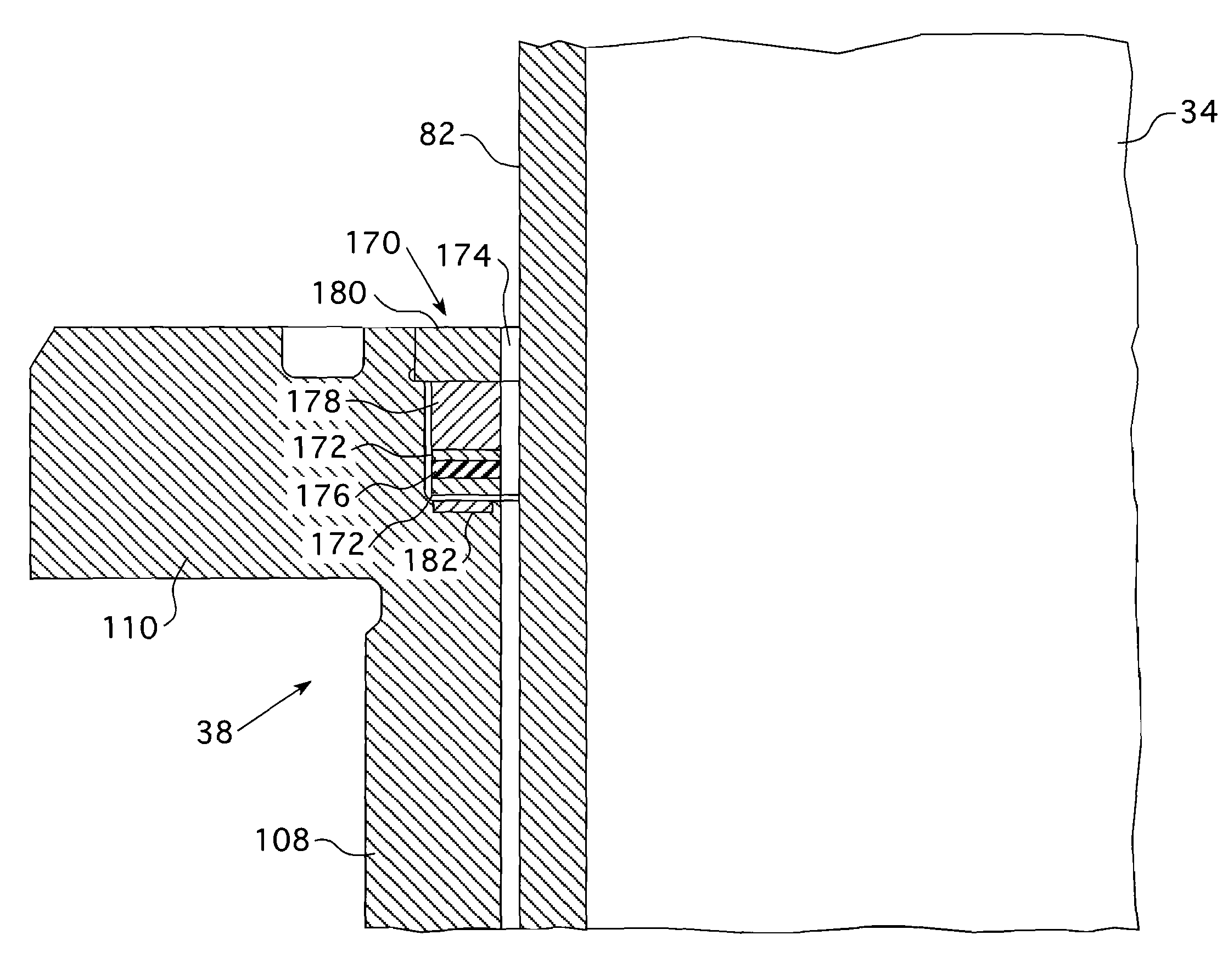
[0044]In accordance with the present invention, as shown in FIGS. 5 and 7-9, an additional seal 170 is advantageously provided in the pump 14 as a backup safety or shutdown device which is actuatable to prevent excessive leakage along the shaft 34 between it and the seal assemblies 38, 40, 42 of the pump in the event of a loss of seal cooling. As shown in FIG. 5, the shutdown seal 170 is situated in a machined groove in the annular opening in the insert 110 of the primary number 1 seal 38. The shutdown seal is characterized by a “split ring”172 that is designed (i) to surround the shaft 34 with an annulus 174 therebetween during normal operation and (ii) to constrict against the shaft 34 when the shaft significantly slows or stops rotating after a loss of seal cooling. The split ring 172 is a single piece discontinuous ring member that is split axially and the confronting ends are maintained in a spaced relationship by a spacer 176 during normal pump operation. In FIG. 5 the opposin...

first embodiment

[0045]FIG. 5 depicts a shutdown seal 170 in accordance with this invention installed in the reactor coolant pump of FIG. 4. The shutdown seal of FIG. 5 is designed to activate after a loss of seal cooling and seal leak-tight when the pump shaft 34 slows down or is not rotating. The shutdown seal is located within the pump housing, encircling the shaft 34. In the case of the type of reactor coolant pump illustrated in FIGS. 2-4, the #1 seal insert may be modified by machining out a portion of the inner diameter at the top flange. Until activated, the shutdown seal 170 is substantially completely contained within the space once taken up by the #1 insert prior to modification, thus substantially unaltering the annulus 174 between it and the shaft 34. In this way coolant flow through the annulus 174 along the shaft 34 is not substantially impeded during normal operation of the rotating equipment.

[0046]The activating portion of the shutdown seal 170 of FIG. 5 is made up of a low melting ...


PUM


Abstract

A thermally actuated shutdown seal for a rotating shaft having a narrow annular fluid flow path surrounding the shaft. The seal surrounds the shaft with the annulus therebetween during normal operation and constricts against the shaft when the shaft slows or stops rotating. The annulus is maintained open during normal operation by a spacer interposed between opposing ends of a split ring. When the shaft stops rotating, the temperature of the annulus rises, which actuates removal of the spacer from the split ring constricting the split ring against the shaft blocking the annulus. The blocked annulus causes a pressure differential across the seal which urges a polymer seal ring, downstream of the split ring against the shaft which seals the annulus. In one embodiment, the spacer is formed of a meltable material. In a second embodiment, the spacer is removed from the split ring by a thermally responsive actuator.

Description

CROSS REFERENCE TO RELATED APPLICATION[0001]This application claims priority to Provisional Application Ser. No. 61 / 121,207, filed Dec. 10, 2009.BACKGROUND OF THE INVENTION[0002]1. Field of the Invention[0003]This invention pertains generally to rotary shaft seals and, more particularly, to a thermally actuated shutdown seal for a centrifugal liquid pump.[0004]2. Description of the Related Art[0005]In pressurized water nuclear power plants a reactor coolant system is used to transport heat from the reactor core to steam generators for the production of steam. The steam is then used to drive a turbine generator for the production of useful work. The reactor coolant system includes a plurality of separate cooling loops, each connected to the reactor core and containing a steam generator and a reactor coolant pump.[0006]The reactor coolant pump typically is a vertical, single stage, centrifugal pump designed to move large volumes of reactor coolant at high temperatures and pressures, f...

Claims


Application Information

Patent Timeline
Patent Type & Authority Patents(United States)
IPC IPC(8): F16J15/00
CPCF16J15/164F16J15/18F16J15/16
Inventor HOWARD, BRUCEHODGSON, JUDITHTALLOS, NICKQUINTY, GLENNJANOCKO, DAVIDBICE, CHARLES
Owner WESTINGHOUSE ELECTRIC CORP
Why Eureka
Try Eureka