Method and device for measuring optical characteristics of an object

a technology of optical characteristics and optical characteristics, applied in the field of diffuse optical imaging, can solve the problems of particularly long acquisition time, and achieve the effect of reducing resources or processing time and increasing the calculation speed

Active Publication Date: 2013-01-22
COMMISSARIAT A LENERGIE ATOMIQUE ET AUX ENERGIES ALTERNATIVES
View PDF3 Cites 18 Cited by
  • Summary
  • Abstract
  • Description
  • Claims
  • Application Information

AI Technical Summary

Benefits of technology

[0021]According to another feature of the invention, the detection is modulated according to an acquisition modulation function designed so that the result of the modulated acquisition is directly an optical characteristic of the object at each point or pixel of the image or an intermediate quantity enabling this feature to be calculated more rapidly than with the prior techniques.
[0022]Thus the modulation of the acquisition carried out upon each illumination makes it possible to obtain, for each pixel, a quantity which is a function of an optical characteristic of interest of the illuminated object without it being necessary to take mathematical processing of the acquisitions so that, with a single acquisition, it is possible to directly obtain a quantity of interest or an intermediate quantity, whereas according to the prior art it was necessary to carry out a large number of acquisitions in order to obtain, for each pixel, a temporal photon distribution histogram, each histogram then having to undergo digital processing so as to obtain the optical quantity of interest.
[0023]It is therefore apparent that the implementation of the method according to the invention makes it possible to substantially reduce the resources or the processing time needed to obtain the optical characteristics of interest.
[0038]Thus, if the acquisition modulation function G(t) can be decomposed into a positive part G+(t) and a negative part G−(t), the first acquisition may be carried out by implementing the positive part G+(t) as acquisition modulation function, whereas the second acquisition may be implemented using the absolute value of the function G−(t) as acquisition modulation function. Thus, the result of the step of generating the third image corresponding to the subtraction of the image of the second acquisition step from the image of the first acquisition step will correspond, for each pixel, to the value that would have been obtained for an acquisition modulated with the function G(t). In this way, it is possible to circumvent the physical impossibilities associated with the acquisition modulation device.
[0042]Thus, by changing the acquisition modulation function at each illumination / acquisition sequence, it is possible to obtain an optical characteristic of interest which can then be used for reconstructing optical quantities of the object scanned.
[0050]According to the invention, the control and acquisition unit is designed to carry out the acquisition outside the phase of light radiation emission by the light source and to control, at each acquisition, the acquisition modulation means according to a continuous, non-sinusoidal and temporal acquisition modulation function. The temporal modulation function, which is a continuous function, is designed so that each modulated acquisition results directly in an optical characteristic of the object at each point or pixel of the image or an intermediate quantity enabling this characteristic to be calculated more rapidly.

Problems solved by technology

This results in a particularly long acquisition time, depending on both the number of acquisitions necessary at each point and on the desired spatial resolution.
Thus, each histogram corresponding to a pixel of the recorded image requires particularly resource-consuming calculations so as to obtain intermediate data as described above—moments and Laplace transform—in order to recover the quantities of interest, namely, for example, the absorption coefficients, the reduced scattering coefficients or the concentration of fluorophores.

Method used


Image

  • Method and device for measuring optical characteristics of an object
  • Method and device for measuring optical characteristics of an object
  • Method and device for measuring optical characteristics of an object

Examples


Embodiment Construction

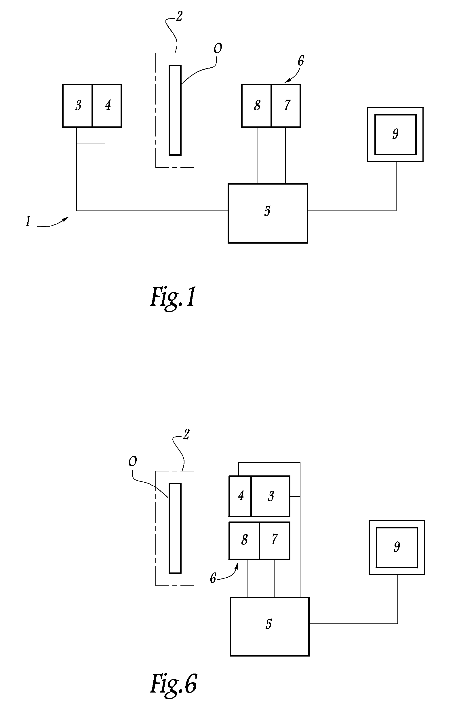
[0065]A measurement device according to the invention, as illustrated in FIG. 1 and denoted in its entirety by the reference 1, comprises a measurement area 2 depicted schematically by the dot-dash lines, in which an object O is placed, which object may be a specimen of biological or nature or else, optical characteristics of which have to be determined. In the case of in vivo measurement, the object O may also be formed by all or part of a living organism, such as a small animal or part of a human body.

[0066]The measurement device 1 comprises a light source 3 designed to emit light radiation toward the measurement area in order to illuminate the object O. The light source 3 is a pulsed source, preferably a subnanosecond pulsed source, and can generate a point of light on at least one face of the object O. It may for example comprise a light source combined with a laser cavity so as to emit pulsed radiation having a wavelength of 635 nm and a pulse repetition frequency of 80 MHz. Th...


PUM


Abstract

Method and device for measuring the multi-dimensional distribution of optical characteristics of an object, by carrying out the following operations:illumination of the object by means of a pulsed light source; andacquisition of an image by modulated detection of light rays coming from the object consecutively to the illumination, the detection being modulated according to an acquisition modulation function G(t) which is continuous, non-sinusoidal and temporal, the acquisition taking place outside the phase of illumination by the light source.

Description

[0001]This application is a U.S. national phase application filed pursuant to 35 U.S.C. 119 and claims priority to and benefit of French Patent Application No. 08 57331, filed Oct. 28, 2008.TECHNICAL FIELD[0002]The present invention relates to the technical field of diffuse optical imaging and to its application to diffuse optical fluorescence imaging and to the determination of optical properties of scattering media. The invention may in particular be applied to biological tissue specimens or to animal or human body parts, the dimensions of which are compatible with the penetration depth of the optical radiation used.PRIOR ART[0003]Diffuse optical imaging generally consists in determining the distribution of optical properties of a living or non-living biological object in order to deduce therefrom the existence or absence of a pathology. It may also consist in determining the average optical properties of a medium. This technique may be employed directly on the biological object w...

Claims


Application Information

Patent Timeline
Patent Type & Authority Patents(United States)
IPC IPC(8): G01J1/58G01J1/08
CPCG01N21/4795G01N21/6408G01N21/6456
Inventor GUYON, LAURENTHERVE, LIONEL
Owner COMMISSARIAT A LENERGIE ATOMIQUE ET AUX ENERGIES ALTERNATIVES
Why Eureka
Try Eureka