Imaging device with plural rotating shutters for varying a frame cycle

a technology of rotating shutters and imaging elements, which is applied in the field of imaging devices, can solve the problems of insufficient light blocking period, insufficient reading out of imaging signals, and inflexible shutter speed, and achieve the effects of high shutter speed, low shutter speed, and enhanced flexibility in setting the period and timing of blocking the optical path by the shutter members

Inactive Publication Date: 2013-01-22
SONY CORP
View PDF20 Cites 3 Cited by
  • Summary
  • Abstract
  • Description
  • Claims
  • Application Information

AI Technical Summary

Benefits of technology

[0018]Due to this configuration, the flexibility in setting of the period and timing of the blocking of the optical path by the shutter members is enhanced through the setting of the condition of the blocking of the optical path by two shutter members in the shutter controller. For example, by adjusting the angle formed by two shutter members to thereby set the light-blocking angle small, the period during which light is not blocked by the shutter members in the one-frame imaging period is increased. That is, the so-called shutter speed can be set low. On the other hand, by adjusting the angle formed by two shutter members to thereby set the light-blocking angle large, the period during which light is blocked by the shutter members in the one-frame imaging period is increased, which allows light blocking corresponding to a high shutter speed. Therefore, the configuration according to the embodiment of the present invention is suitable for an imaging device that can carry out change setting of the frame rate and exposure time of imaging by an imaging element.
[0019]In the embodiment of the present invention, because of the configuration that allows adjustment of the condition of blocking of the optical path to the imaging element by two shutter members, the ratio between the light-blocking time and the exposure time can be adjusted, which can freely set a state suitable for the frame rate, the shutter speed, and so on at that time. In particular, if an electronic shutter is also used, the exposure aperture angle can be changed in a wide adjustment range of 0° to 270° even with two shutter members that offer the benefit of simultaneity of the exposure by the mechanical shutter. In the related art, three or more shutter members are needed in order to obtain the adjustment range of the exposure aperture angle above the range of 0° to 180°. In contrast, the embodiment of the present invention can simplify the configuration.
[0020]Because the configuration can be simplified, cost reduction, weight reduction, and reliability enhancement for the imaging device can be correspondingly achieved. Furthermore, simplification and weight reduction of the structure of the rotational part can reduce the power necessary for the rotational driving, which can achieve reduction in the power consumption of the imaging device. Moreover, it is also possible to easily handle sudden change in the frame cycle, which can widen the range of the video representation.

Problems solved by technology

If light blocking and exposure for an imaging element are alternately carried out by rotating one shutter blade, a problem arises that the timing of the light blocking is settled in a somewhat fixed manner and the flexibility in the shutter speed, which corresponds to the accumulation period of the charge for obtaining the image signal of one frame, is limited.
However, if the angle range of light blocking by the shutter blade is set smaller, the period during which light is blocked within the one-frame period is also correspondingly shortened, which causes a possibility that the light-blocking period is insufficient to read out the signal obtained in the imaging element.
In such variable speed ramping, the shutter blade is often an obstacle depending on the setting of the cycle of the imaging.

Method used


Image

  • Imaging device with plural rotating shutters for varying a frame cycle
  • Imaging device with plural rotating shutters for varying a frame cycle
  • Imaging device with plural rotating shutters for varying a frame cycle

Examples


Embodiment Construction

[0031]One embodiment of the present invention will be described below in the following order with reference to the accompanying drawings.

[0032]1. Entire Configuration Example of Imaging Device (FIG. 1)

[0033]2. Description of Shutter Mechanism as Premise (FIGS. 7 to 10D)

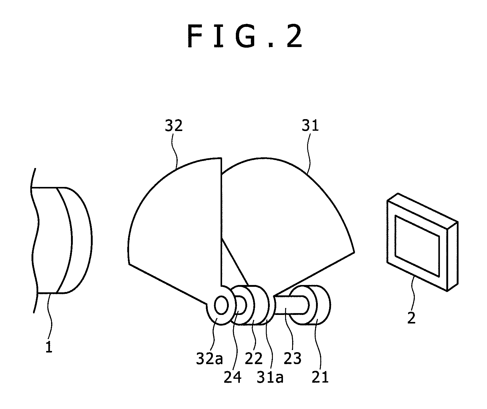
[0034]3. Description of Shutter Mechanism of Present Embodiment (FIGS. 2 to 4C)

[0035]4. Examples of Imaging State of Present Embodiment (FIGS. 5A to 5F and FIGS. 6A to 6E)

[0036]5. Description of Modification Examples of Embodiment

[Entire Configuration Example of Imaging Device]

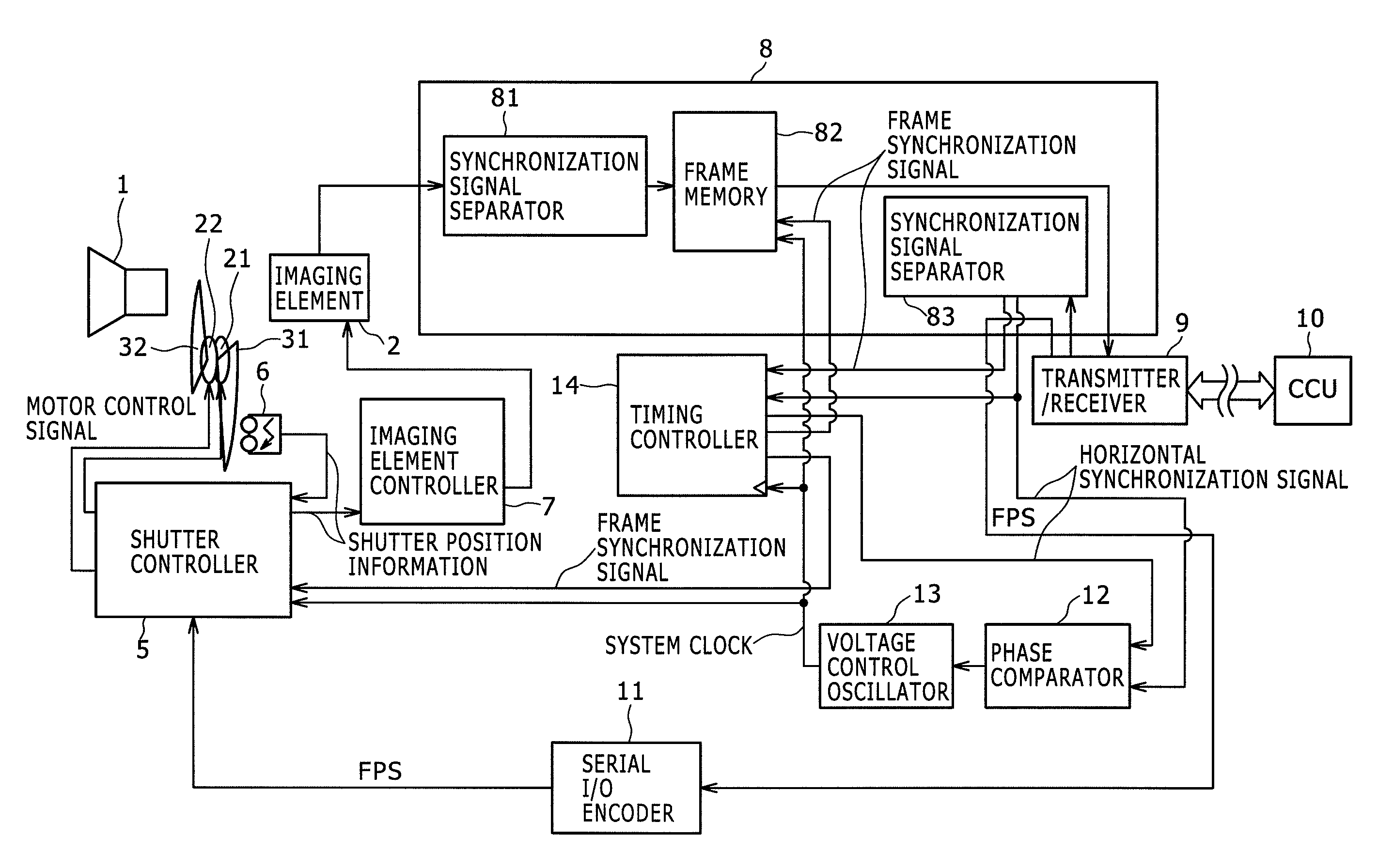
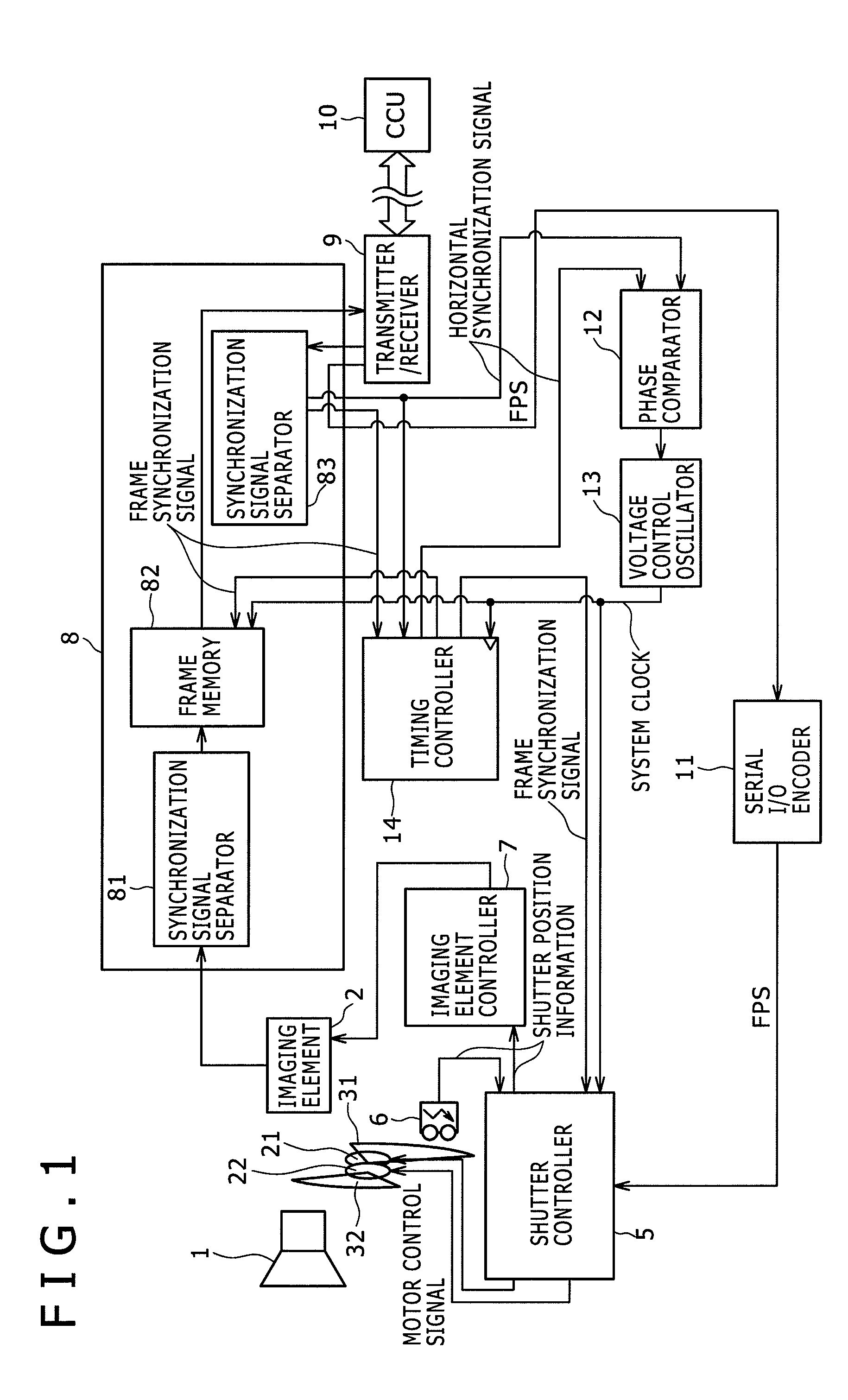
[0037]FIG. 1 is a diagram showing a configuration example of an imaging device according to the present embodiment. The imaging device of the present embodiment is connected to a camera control unit 10 (hereinafter, referred to as the CCU 10). A video signal and a control signal are exchanged between the imaging device and the CCU 10 based on e.g. the high definition-serial digital interface (HD-SDI) standard.

[0038]The frame synchronization freq...


PUM


Abstract

Disclosed herein is an imaging device including an imaging element, an imaging controller, first and second shutter members, and a shutter controller. The imaging element carries out photoelectric conversion of subject image light incident through a lens and produces an imaging signal. The imaging controller controls readout of the imaging signal and carries out control of change setting of a frame cycle of imaging. The shutter members are disposed on an optical path of image light incident and can set a state in which incident light on the imaging element is blocked and a state in which incident light on the imaging element is not blocked. The shutter controller sets a timing at which the optical path is blocked by the first shutter member and a timing at which the optical path is blocked by the second shutter member.

Description

BACKGROUND OF THE INVENTION[0001]1. Field of the Invention[0002]The present invention relates to an imaging device formed as a video camera, and particularly to an imaging device that carries out imaging with combination of a mechanical shutter and an electronic shutter.[0003]2. Description of the Related Art[0004]In an imaging device employing a frame-transfer (FT) charge coupled devices (CCD) image sensor as its imaging element, the image area (light receiving part) is shielded from light during signal charge readout. Furthermore, in an imaging device employing a complementary metal oxide semiconductor (CMOS) image sensor, the image area is shielded from light during charge readout in order to achieve simultaneity of signal charge accumulation.[0005]A scheme of using a rotary shutter is known as a method for shielding the image area from light. The rotary shutter is obtained by providing a shutter blade that is driven to rotate by a motor between an imaging lens and the imaging el...

Claims


Application Information

Patent Timeline
Patent Type & Authority Patents(United States)
IPC IPC(8): H04N5/238
CPCH04N5/2254H04N5/2353H04N5/341H04N5/3532H04N23/60H04N23/73H04N25/40H04N25/531
Inventor AMANO, RYOSUKE
Owner SONY CORP
Why Eureka
Try Eureka