
Trouble diagnosis device and trouble diagnosis method for NOx sensor

a technology of trouble diagnosis device and nox sensor, which is applied in the direction of electrical control, separation process, instruments, etc., can solve problems such as environmental risk, and achieve the effects of easy determination, enhanced reliability of nox sensor, and easy determination of responsiveness of nox sensor

Active Publication Date: 2013-01-29
BOSCH CORP
View PDF17 Cites 14 Cited by
  • Summary
  • Abstract
  • Description
  • Claims
  • Application Information

AI Technical Summary

Benefits of technology

The present invention provides a trouble determining means for an NOx sensor that can detect if there is a transition in NOx concentration while the exhaust NOx flow rate changes in relation to the engine operation. This allows for the diagnosis of NOx sensor without creating a diagnosis mode and without affecting the driving experience or fuel efficiency. The device sets a reference pattern and a follow pattern to easily determine if the detected NOx concentration follows the variation of the exhaust NOx flow rate. The device can shift to the determination mode when a predetermined condition is satisfied, and a diagnosis under normal operation state can be efficiently performed without frequently repeating the mode. The device stops the determination mode when the exhaust NOx flow rate dips, enhancing the reliability of the diagnosis result. The reference pattern has a delay region where the problem diagnosis can be continued even when the exhaust NOx flow rate is temporarily reduced. This improves the reliability of the NOx sensor and the purification efficiency of the exhaust gas purification system using the NOx sensor.

Problems solved by technology

Particular matter (PM), NOx (NO or NO2), etc. which may have a risk of affecting the environment are contained in exhaust gas discharged from an internal combustion engine such as a diesel engine or the like.

Method used


Image

  • Trouble diagnosis device and trouble diagnosis method for NOx sensor
  • Trouble diagnosis device and trouble diagnosis method for NOx sensor
  • Trouble diagnosis device and trouble diagnosis method for NOx sensor

Examples


first embodiment

[0044]1. Trouble Diagnosis Device for NOx Sensor

[0045](1) Whole Construction of Exhaust Gas Purification System

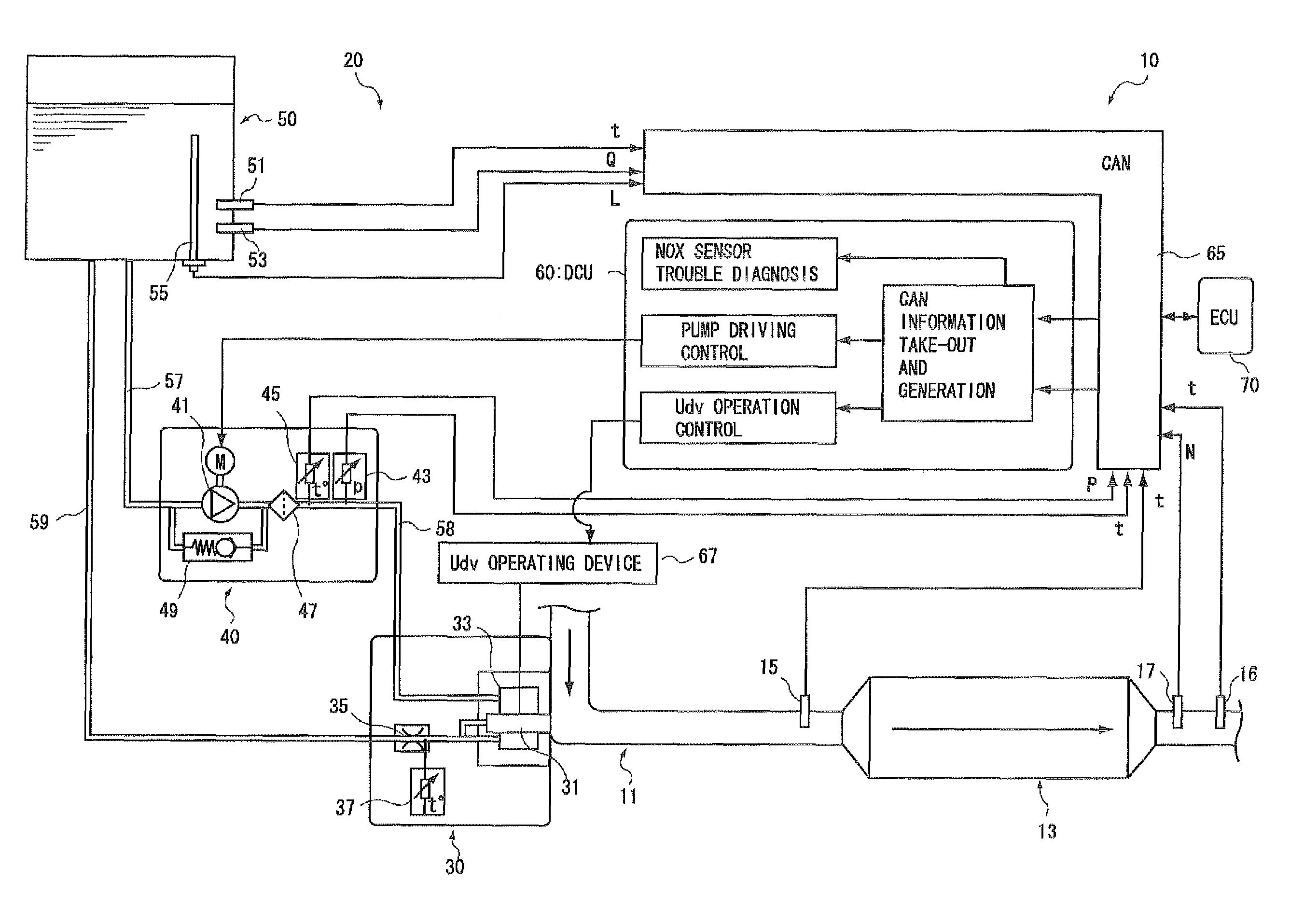
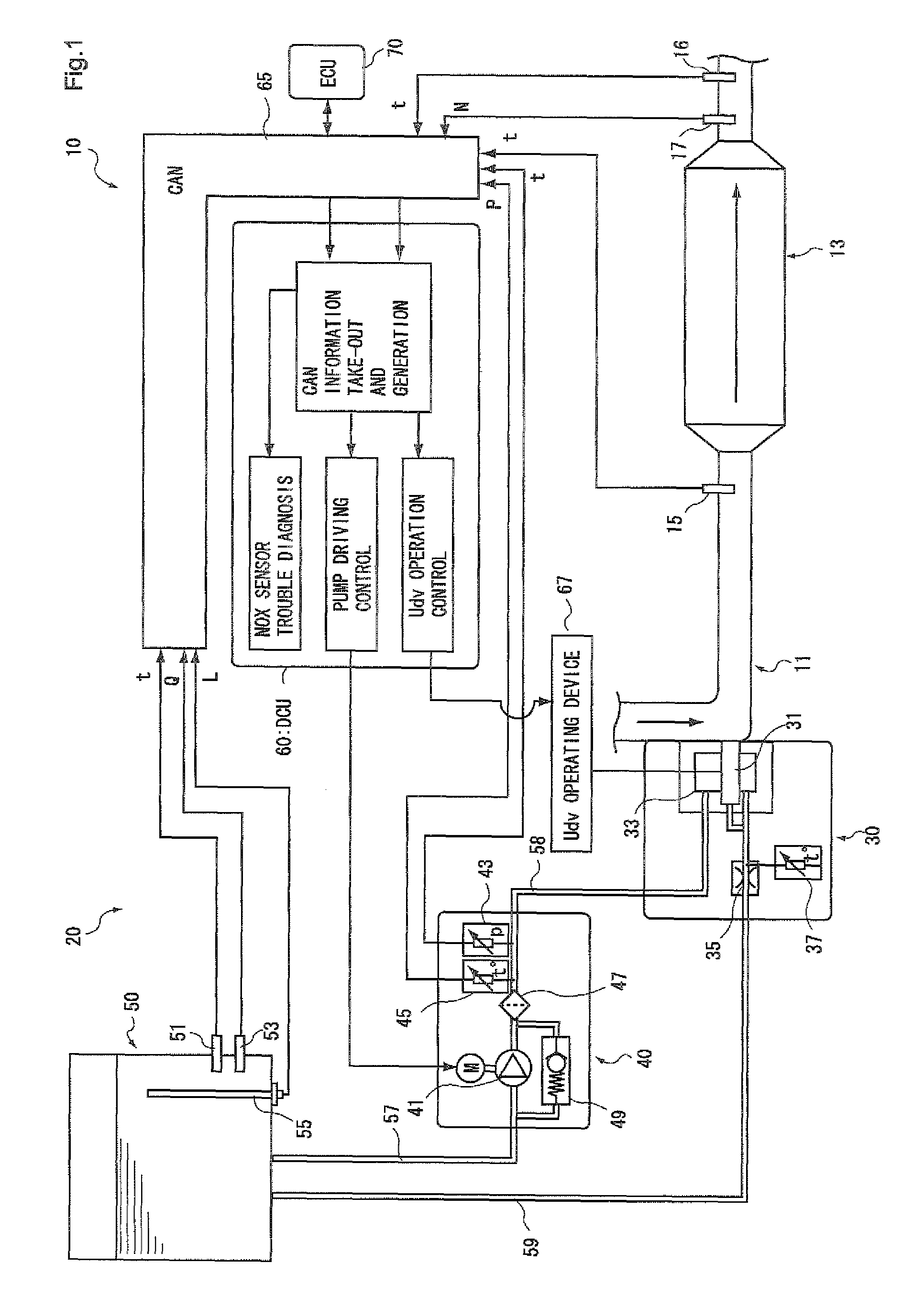
[0046]First, an example of the construction of an exhaust gas purification system (hereinafter referred to as “system” in some cases) having an NOx sensor trouble diagnosis device according to a first embodiment of the present invention will be described with reference to FIG. 1.

[0047]An exhaust gas purification system 10 shown in FIG. 1 uses urea water solution as reducing agent, and passes exhaust gas through NOx catalyst 13 together with the reducing agent to selectively reduce NOx. The exhaust gas purification system 10 has a NOx catalyst 13 which is disposed at some point of an exhaust gas passage 11 connected to an internal combustion engine and selectively reduces NOx contained in exhaust gas, and a reducing agent supply device 20 containing a reducing agent injection valve 31 for injecting reducing agent into the exhaust gas passage 11 at the upstream side of the NO...

second embodiment

[0109]The NOx sensor trouble diagnosis method according to this embodiment is an NOx sensor trouble diagnosis method in an SCR system in which the capacity of the NOx catalyst is relatively small as described above. That is, in this embodiment, the time period from the time when the exhaust NOx flow rate increases till the time when the detected NOx flow rate detected by the NOx sensor disposed at the downstream side of the NOx catalyst follows is short, and the lapse time of the timer 2 is set to be longer than the lapse time of the timer 5. Hereinafter, points different from those of the first embodiment will be mainly described along the flowcharts of FIGS. 7 to 9.

[0110]In this embodiment, the same steps S100 to S113 as the first embodiment are executed until the timers 2, 3, 5 and 6 are actuated (see FIG. 4). After the timers 2, 3, 5 and 6 are actuated, steps S154 to S161 are executed as in the case of the steps S114 to S121 of the first embodiment (see FIG. 5), and then the pro...


PUM


Abstract

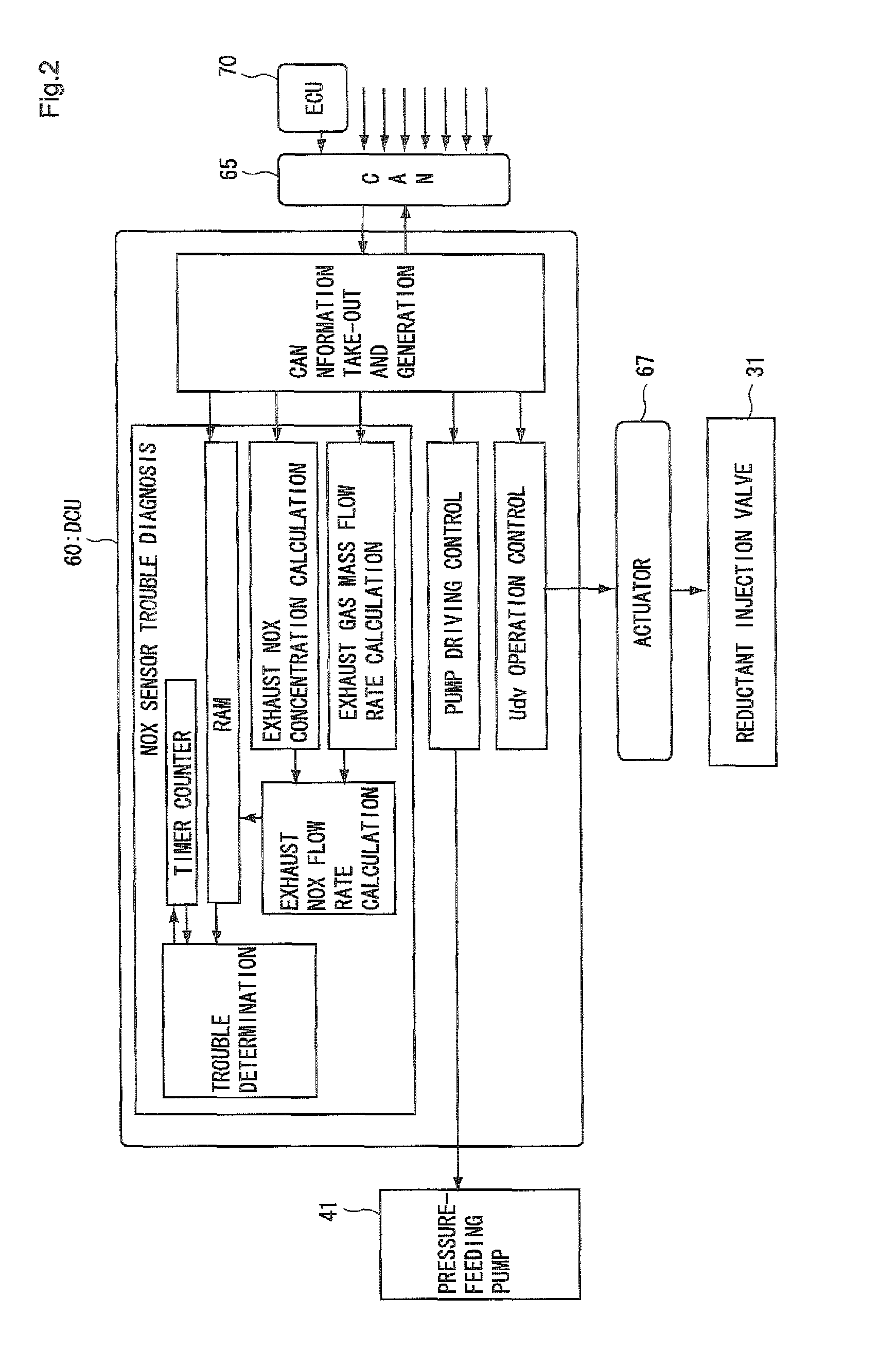
A trouble diagnosis device and method for an NOx sensor for determining abnormality of an NOx sensor used in an exhaust gas purification system. The device can perform a trouble diagnosis without forcedly creating a diagnosis mode during operation of an internal combustion engine and without deterioration of drivability or fuel consumption. The device detects the time-lapse variation of the exhaust NOx flow rate suitable for diagnosis in a normal operation mode and determines whether the NOx sensor responds with following this variation.

Description

TECHNICAL FIELD[0001]The present invention relates to a trouble diagnosis device for an NOx sensor and a trouble diagnosis method for an NOx sensor, and particularly relates to a trouble diagnosis device for an NOx sensor and a trouble diagnosis method for an NOx sensor to enhance the precision of trouble diagnosis for the NOx sensor.BACKGROUND ART[0002]Particular matter (PM), NOx (NO or NO2), etc. which may have a risk of affecting the environment are contained in exhaust gas discharged from an internal combustion engine such as a diesel engine or the like. An exhaust gas purification system having an NOx catalyst disposed in an exhaust gas passage is known as an exhaust gas purification system used to purify NOx out of the above materials.[0003]An exhaust gas purification system using NOx storage catalyst and an SCR (Selective Catalytic Reduction) system using selective reduction catalyst are known as such an exhaust gas purification system. Accordingly to the exhaust gas purifica...

Claims


Application Information

Patent Timeline
Patent Type & Authority Patents(United States)
IPC IPC(8): F01N11/00G01M15/10
CPCF01N3/0807F01N11/00F02D41/146F02D41/1461F02D41/1462F02D41/222F01N2560/026F01N2900/0416F01N2900/14Y02C20/10Y02T10/40Y02T10/20Y02T10/47Y02T10/12B01D53/86B01D53/94F01N3/08F01N3/18
Inventor KITAZAWA, EIICHI
Owner BOSCH CORP
Learn More