
Brightness enhancement film and backlight module

a technology of enhancement which is applied in the field of optical film and backlight module, can solve the problems that the environmental light lb>2/b> cannot be successfully applied to the display light of the liquid crystal panel, and achieve the effect of improving the optical brightness enhancement effect and effectively utilizing the environmental ligh

Inactive Publication Date: 2013-01-29
CORETRONIC
View PDF11 Cites 5 Cited by
  • Summary
  • Abstract
  • Description
  • Claims
  • Application Information

AI Technical Summary

Benefits of technology

[0009]The invention provides a brightness enhancement film capable of effectively utilizing the environmental light and providing a relatively better optical brightness enhancement effect.
[0010]The invention also provides a brightness enhancement film capable of effectively utilizing the environmental light and having the aforementioned advantages.
[0011]The invention further provides a backlight module having the aforementioned brightness enhancement film capable of increasing the total brightness of the backlight module, further decreasing the power consumption of the backlight module and having the advantage of environmental protection and energy conservation.
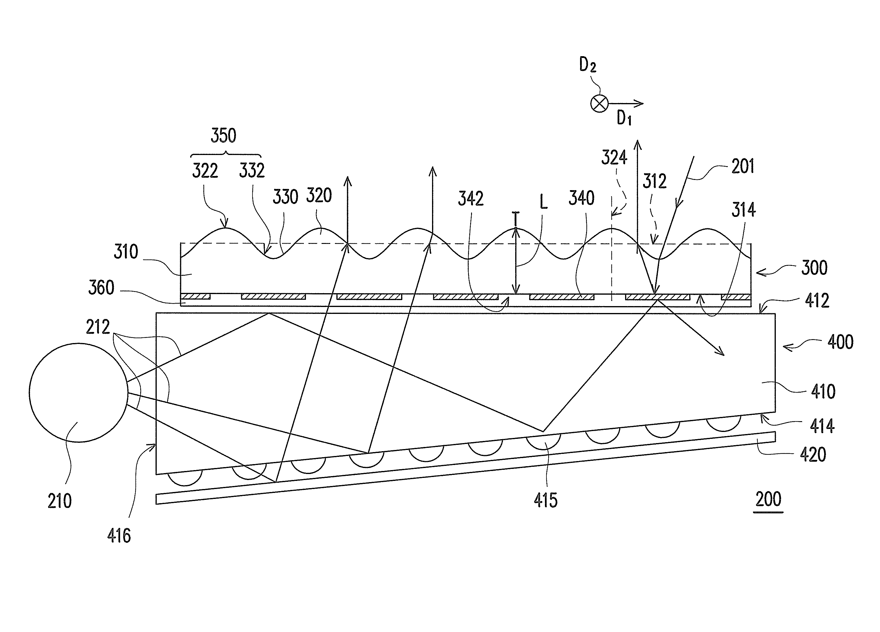
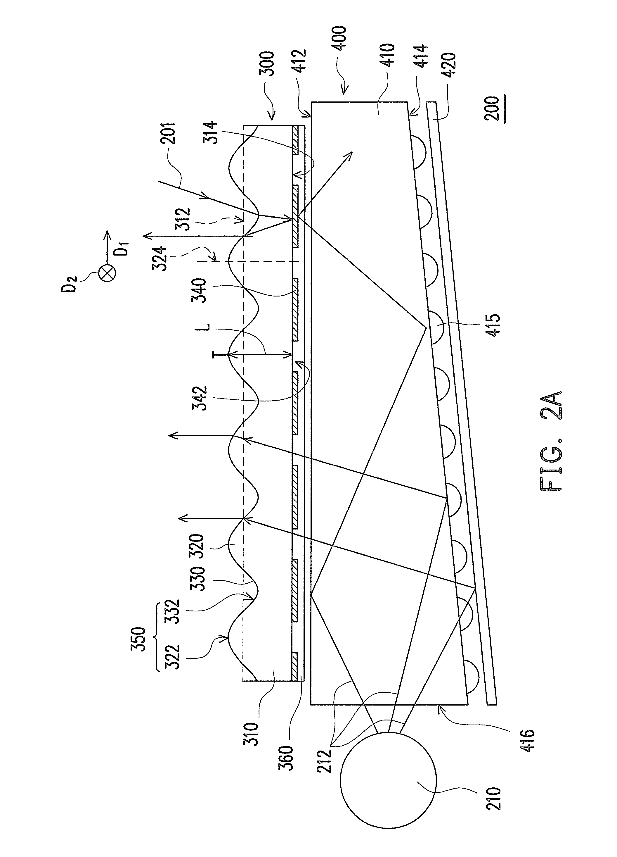
[0016]In summary, the embodiment or the embodiments of the invention may have at least one of the following advantages. Since the convex lens portions and the concave lens portions are disposed on the first surface, the light distribution of the light transmitted out of the first surface is more convergent and close to the direction perpendicular to the first surface after the external light is transmitted into the interior of the brightness enhancement film and is reflected by the reflective layer. Therefore, the total brightness of the backlight module using this brightness enhancement film may be effectively increased. Moreover, the first titled portions and the connecting portions connecting the first titled portions are disposed on the second surface so that the light distribution of the external light transmitted out of the first surface is convergent and close to the direction perpendicular to the first surface. Hence, the total brightness of the backlight module, using this brightness enhancement film may be effectively increased. Further, the first titled portions, the second titled portions, and the connecting portions connecting the first titled portions and the second titled portions are disposed on the second surface, and the aforementioned arrangement may achieve the aforementioned brightness enhancement effect. Therefore, the total brightness of the backlight module using this brightness enhancement film may be effectively increased.

Problems solved by technology

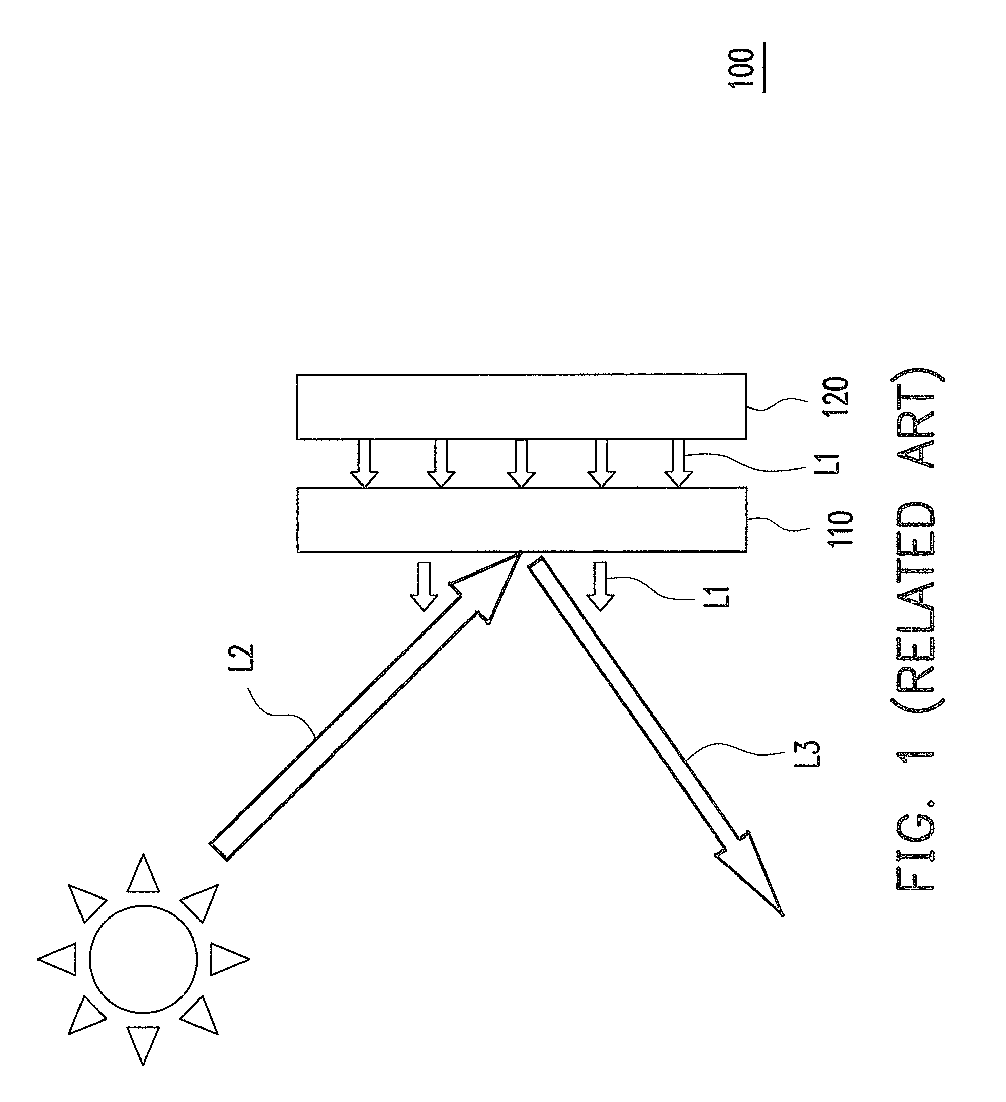
However, by using the aforementioned light guide plate or diffusion film, the environmental light L2 may still not be successfully applied to the display light of the liquid crystal panel 110.

Method used


Image

  • Brightness enhancement film and backlight module
  • Brightness enhancement film and backlight module
  • Brightness enhancement film and backlight module

Examples


Embodiment Construction

[0028]In the following detailed description of the preferred embodiments, reference is made to the accompanying drawings which form a part hereof, and in which are shown by way of illustration specific embodiments in which the invention may be practiced. In this regard, directional terminology, such as “top,”“bottom,”“front,”“back,” etc., is used with reference to the orientation of the Figure(s) being described. The components of the invention may be positioned in a number of different orientations. As such, the directional terminology is used for purposes of illustration and is in no way limiting. On the other hand, the drawings are only schematic and the sizes of components may be exaggerated for clarity. It is to be understood that other embodiments may be utilized and structural changes may be made without departing from the scope of the invention. Also, it is to be understood that the phraseology and terminology used herein are for the purpose of description and should not be ...


PUM


Abstract

A brightness enhancement film including a light transmissive substrate, convex lens portions, concave lens portions, and a reflective layer is provided. The light transmissive substrate has a first surface and a second surface opposite to the first surface. The convex lens portions are disposed on the first surface. Each of the convex lens portions has a curved convex surface facing away from the light transmissive substrate. The concave lens portions are disposed on the first surface. The convex lens portions and the concave lens portions are alternately arranged. Each of the concave lens portions has a curved concave surface facing away from the light transmissive substrate. A wavy continuous curve surface is formed by the curved convex surfaces and the curved concave surfaces. The reflective layer is disposed on the second surface and has light passing openings respectively on the optical axes of the convex lens portions.

Description

CROSS-REFERENCE TO RELATED APPLICATION[0001]This application claims the priority benefit of Taiwan application serial no. 98142750, filed on Dec. 14, 2009. The entirety of the above-mentioned patent application is hereby incorporated by reference herein and made a part of this specification.BACKGROUND OF THE INVENTION[0002]1. Field of the Invention[0003]The invention relates to an optical film and a backlight module using the optical film, and particularly to a brightness enhancement film (BEF) and a backlight module using the brightness enhancement film.[0004]2. Description of Related Art[0005]With the progress in display techniques, the flat panel display has become the mainstream among various display devices and replaces the conventional cathode ray tube (CRT). Among the various flat panel displays, the liquid crystal display (LCD) has been deeply favored by the consumers for usage and has been widely used.[0006]FIG. 1 is a schematic diagram of a conventional LCD. As shown in FI...

Claims


Application Information

Patent Timeline
Patent Type & Authority Patents(United States)
IPC IPC(8): F21V5/00
CPCG02B3/0056G02B5/0215G02B5/045G02F2001/133607G02F1/133607
Inventor WENG, CHAO-HUNGSHIAU, TZENG-KE
Owner CORETRONIC
Learn More