Wind-driven electric power generation system adapted for mounting along the side of vertical, man-made structures such as large buildings

a technology of wind power generation and man-made structures, applied in the direction of energy harvesting concepts, electric generator control, machines/engines, etc., can solve the problems of inability to deploy large-scale electric wind generators on the top of large buildings, system size and stability difficulties of wind power generation systems, and achieve the effect of low manufacturing cost and less expensiv

Active Publication Date: 2013-01-29
MDL ENTERPRISES
View PDF12 Cites 4 Cited by
  • Summary
  • Abstract
  • Description
  • Claims
  • Application Information

AI Technical Summary

Benefits of technology

[0013]In accordance with yet another feature of the present invention, at least one fixed helical vane can be integrated into the inner surface of the tubular housing in a spiral, adapted to further direct fluid captured in the housing into a spiraled fluid flow and more directly focus the fluid's energy onto fan blades associated with an electrical alternator located at or near the end of the at least one fixed helical vane. A second end of the tubular housing can enable fluid to be exhausted from the tubular housing once it has passed through fan blades associated with the electrical alternator.
[0026]Another benefit of the alternator of this embodiment is with its potentially low manufacturing cost. The conductor coils can be located on or integrated within the tubular housing peripherally to a magnetic field emitting rotor upon final assembly. The manufacturing reproducibility of the design of the radial, slotless alternator is therefore less expensive and more practical for enable fluid flow there through in accordance with the present invention. Although the radial, slotless alternator can be incorporated into working embodiments of the present invention, other alternator designs can still operate well within fluid power generating systems described herein without limitation.

Problems solved by technology

The wind power generation system faces some difficulty in its stability due to fluctuation in direction and speed of air.
It is unfortunate that such systems must be so large, which is a main point of contention by many communities and makes deployment of large-scaled electric wind generators on the top of large buildings infeasible.

Method used


Image

  • Wind-driven electric power generation system adapted for mounting along the side of vertical, man-made structures such as large buildings
  • Wind-driven electric power generation system adapted for mounting along the side of vertical, man-made structures such as large buildings
  • Wind-driven electric power generation system adapted for mounting along the side of vertical, man-made structures such as large buildings

Examples


Embodiment Construction

[0043]The particular values and configurations discussed in these non-limiting examples can be varied and are cited merely to illustrate at least one embodiment and are not intended to limit the scope thereof.

[0044]“Fan” or “fan blade” are commonly used in association with wind or airflow but as referred to herein should also be interpreted to include the meaning associated with “propeller” or “propeller blades” which are terms commonly used when referring to water flow as a fluid medium.

[0045]“Alternator” as used herein should also be interpreted to include “generator” as a means for producing electrical energy.

[0046]“Fluid” when and as used herein should be interpreted to include wind, airflow caused by prevailing winds forced against the sides of buildings, and updraft air flow or updraft wind caused by prevailing wind pushing against the sides of buildings.

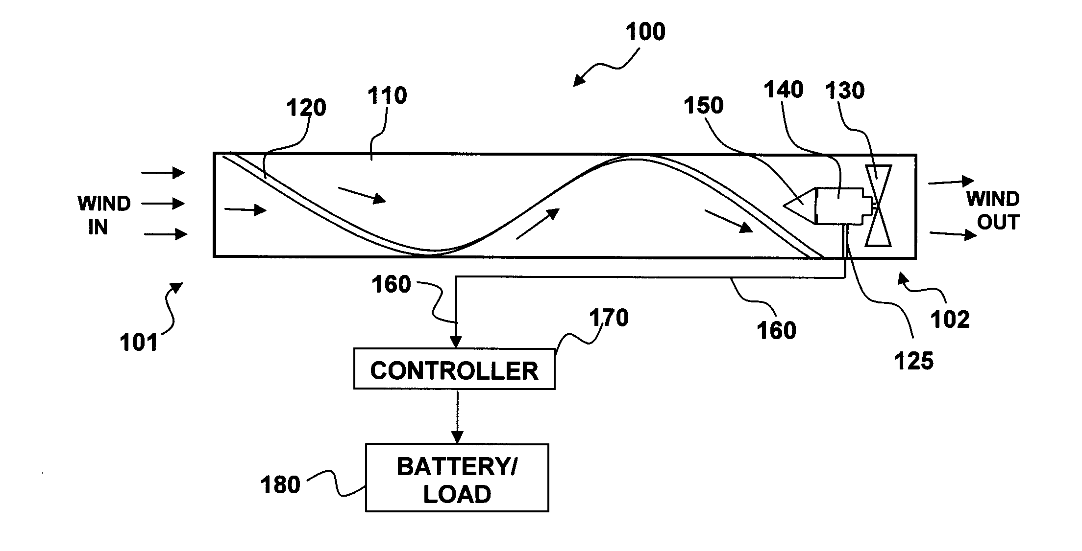
[0047]FIG. 1 illustrates a block diagram of a wind driven electrical power generating system 100, which can be implemented i...


PUM


Abstract

A updraft wind powered electrical generator system mountable to sides of a vertical, man-made structures facing prevailing winds. The updraft system includes a tubular housing that can include at least one fixed helical vane formed onto the inner surfaces of the tubular housing in a spiral and adapted to direct wind into a spiraled flow and focus fluid onto a fan blade assembly associated with an alternator system and located within the tubular housing before a system exhaust. A generator cone can be mounted near the center and front of the fan blade assembly facing wind passing through the tubular housing. As wind passes over the generator cone it experiences compression between the generator cone and housing resulting in increased pressure and velocity of the fluid, thereby increasing rotational speed of the generator blades and generator as the compressed, spiraled fluid passes through the blades and exits the tubular housing.

Description

RELATED APPLICATIONS INCORPORATED BY REFERENCE[0001]This patent application is related to and claims priority as a continuation-in-part patent application to Ser. No. 12 / 058,764, filed Mar. 31, 2008, entitled “WIND-DRIVEN ELECTRIC POWER GENERATION SYSTEM”, which also claims priority as a continuation to provisional patent application 60 / 921,331, filed Mar. 31, 2007 and to Ser. No. 12 / 127,508, filed May 27, 2008, entitled “Fluid Driven Electrical Power Generation System”, which also claims priority to provisional patent application 60 / 953,206, filed Jul. 31, 2007, all herein incorporated by reference herein.TECHNICAL FIELD[0002]The present invention is generally related to renewable energy systems. More particularly, the present invention is related to wind powered electrical generation systems adapted for fixed electrical power generation systems and side of building mountable applications.BACKGROUND OF THE INVENTION[0003]Wind is a force of nature that surrounds large buildings and ...

Claims


Application Information

Patent Timeline
Patent Type & Authority Patents(United States)
IPC IPC(8): F03D9/00
CPCB60K16/00F03D1/04F03D9/002B60K2016/006F05B2240/132F05B2240/941Y02B10/30Y02E10/465Y02B10/70Y02E10/725F03D9/25Y02E10/728F03D9/37Y02E10/46Y02E10/72Y02T10/90
Inventor ORTIZ, LUIS M.BACA, ANTHONY MICHAELWICHERS, DONALD
Owner MDL ENTERPRISES
Why Eureka
Try Eureka