Method and device for producing a metal strip by continuous casting and rolling

a technology of continuous casting and metal strips, applied in the field of continuous casting and rolling, can solve the problems of not finding commercial success, difficult control of rolling trains and temperature control through the whole installation, and both methods, so as to reduce the breakdown rate of the installation and avoid rolling damage

Active Publication Date: 2013-02-05
SMS DEMAG AG
View PDF23 Cites 10 Cited by
  • Summary
  • Abstract
  • Description
  • Claims
  • Application Information

AI Technical Summary

Benefits of technology

[0039]The rolling of strip tail ends and thus roll damage can be avoided or reduced.
[0040]The breakdown rate of the installation can be reduced, and strips with height defects* can be avoided.

Problems solved by technology

Continuous rolling from the casting heat has long been known but has not yet found commercial success.
The rigid connection of the continuous casting installation and the rolling train and temperature control through the whole installation have proven difficult to control.
Both methods, i.e., on the one hand, continuous casting and rolling and, on the other hand, discontinuous casting and rolling, are difficult to combine due to the circumstances described above.

Method used


Image

  • Method and device for producing a metal strip by continuous casting and rolling
  • Method and device for producing a metal strip by continuous casting and rolling
  • Method and device for producing a metal strip by continuous casting and rolling

Examples


Embodiment Construction

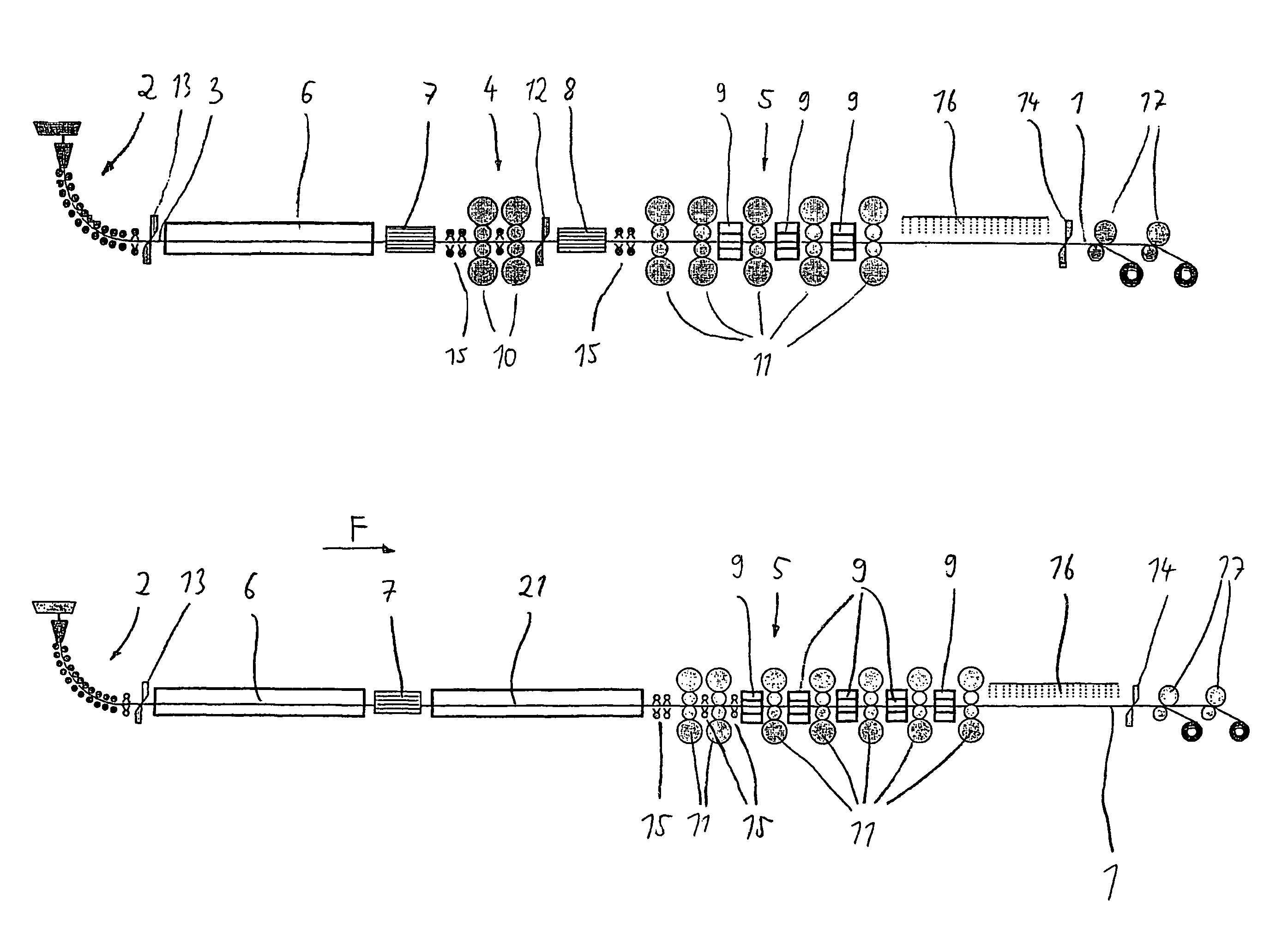
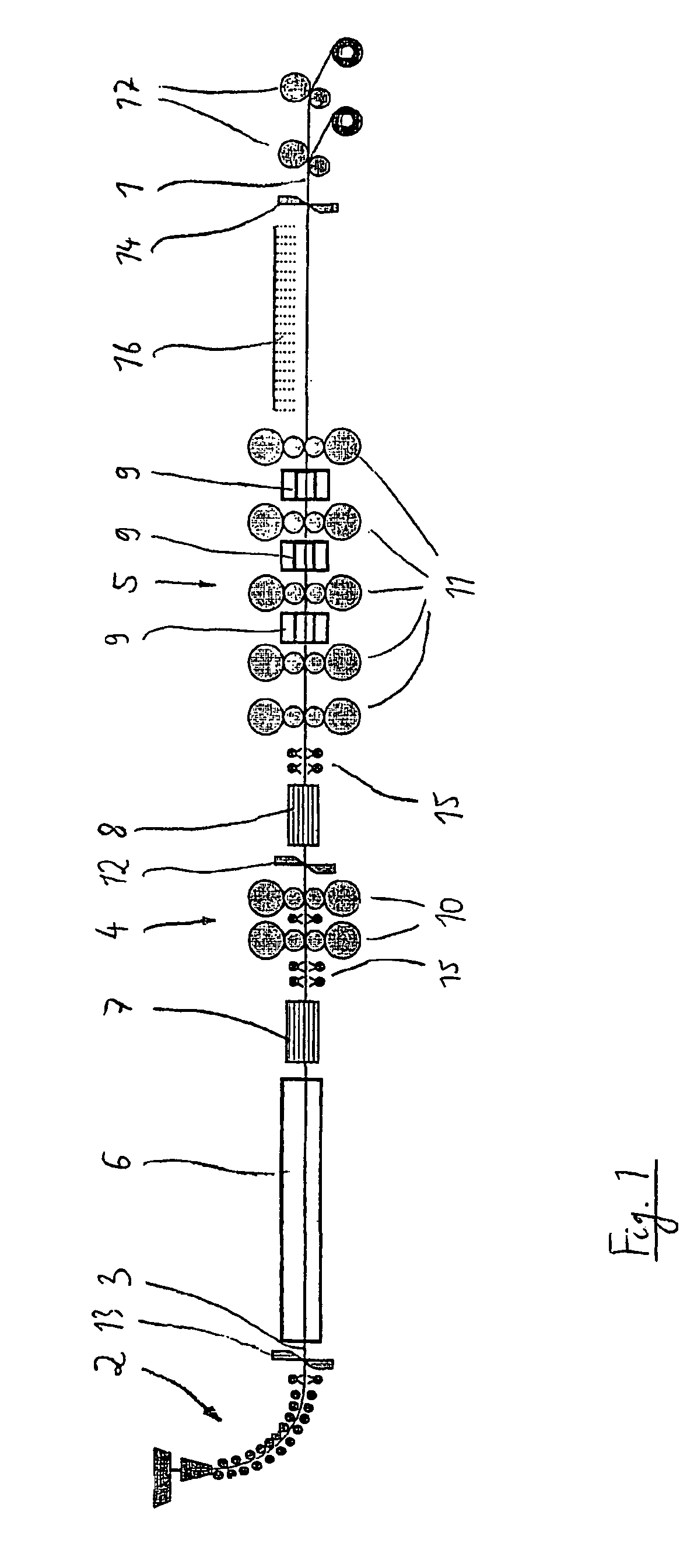
[0048]FIG. 1 shows a direct strand reduction installation, in which a metal strip 1 is produced by first casting a thin slab 3 in a casting machine 2 of a type that is already well known and then conveying it to a rolling train 4, 5, which in the present case consists of a roughing train 4 and a finishing train 5.

[0049]In order to allow both continuous operation and discontinuous operation in accordance with the above discussion, both a holding furnace 6 and an induction furnace 7 are provided upstream of the rolling train 4, 5. The two furnaces 6, 7 are operated by a suitable control system (not shown) in such a way that the correct strip temperatures are present for the two modes of operation. The open-loop or closed-loop control systems required for this are sufficiently well known from the prior art.

[0050]The holding furnace 6 installed downstream of the casting machine 2 can be a conventionally gas-fired furnace. The order in which the holding furnace 6 and induction furnace 7 ...


PUM

PropertyMeasurementUnit
thicknessaaaaaaaaaa
thicknessesaaaaaaaaaa
thicknessaaaaaaaaaa

Abstract

A method and a device for producing a metal strip by continuous casting and rolling, in which a thin slab is initially cast into a casting machine, and is subsequently rolled in at least one rolling train using primary heat from the casting cycle. The cast thin slab is passed between the casting machine and the at least one rolling train and at least one holding oven as well as at least one induction oven. The holding oven and the induction oven are activated or deactivated according to a selected mode of operation, that is, a first mode of operation for the continuous production of the metal strip and a second mode of operation for the discontinuous production of the metal strip.

Description

BACKGROUND OF THE INVENTION[0001]The invention concerns a method for producing metal strip by direct strand reduction, in which a thin slab is first cast in a casting machine and then rolled in at least one rolling train with utilization of the primary heat of the casting process. The invention also concerns an installation for producing metal strip by direct strand reduction.[0002]Installations of this type are known as thin slab-thin strip direct strand reduction installations and are referred to as CSP installations.[0003]Continuous rolling from the casting heat has long been known but has not yet found commercial success. The rigid connection of the continuous casting installation and the rolling train and temperature control through the whole installation have proven difficult to control.[0004]EP 0 286 862 A1 and EP 0 771 596 B1 disclose methods and installations for continuous rolling from the casting heat. In these cases, the casting process and the rolling process are direct...

Claims


Application Information

Patent Timeline
Patent Type & Authority Patents(United States)
IPC IPC(8): B22D11/12B22D27/02B22D11/14B22D11/126B21B1/46
CPCB21B1/46C21D8/0426C21D9/48C21D9/60B21B1/463B21B1/466B21B13/22B21B15/005B21B45/004Y10T29/49991B21B2201/10C21D11/00Y10T29/49989B21B45/008Y02P10/25Y02P70/10H05B6/10
Inventor ROSENTHAL, DIETERKRAMER, STEPHANSEIDEL, JURGENBENFER, FRANK
Owner SMS DEMAG AG
Why Eureka
Try Eureka