Method and device for controlling the synchronization of cylinder/piston units and for reducing pressure peaks during forming and/or fineblanking on a fineblanking or stamping press

a technology of cylinder/piston unit and synchronization device, which is applied in the direction of mechanical equipment, forging hammers, and safety devices, etc., can solve the problems of parts to undesirable deformation, inability to pick up the pressure surge, and increase the impairment of the synchronization between the main ram of the press, so as to improve the synchronization properties of the cylinder/piston unit and reduce the pressure peaks

Active Publication Date: 2013-02-19
FEINTOOL INT HLDG
View PDF14 Cites 4 Cited by
  • Summary
  • Abstract
  • Description
  • Claims
  • Application Information

AI Technical Summary

Benefits of technology

[0013]Given this prior art, the basic object of the invention is to provide a method and a device for controlling the synchronization of cylinder / piston units and at least one main ram and for reducing pressure peaks during forming and / or fineblanking on fineblanking or stamping presses, which discharges any recoil caused by the impact between the punch and the workpiece, independently of quantity, from the controlling of the working pressure of the hydraulic fluid, bringing about a marked improvement in the synchronization properties of the cylinder / piston units and the main ram through a constant pressure characteristic in the hydraulic system including with high cycle times and speeds.
[0014]The method according to the invention is characterized in that first of all the cylinder / piston units are continuously maintained at a preadjustable cushion pressure by means of a first accumulator supplied from a low-pressure source and that the cylinder / piston units are then subjected to a preadjustable displacement pressure from a connectable high-pressure source, with said pressure being set to a pressure varying between cushion pressure and pressure for forming and / or blanking by supplying a separate control oil quantity to a second accumulator via a central control unit, whereby a rise in pressure caused by the impact between the tool and the workpiece is regulated, independently of quantity, from the pressure to a permissible set pressure by discharging a significant part of the pressure pulse into a separate tank, and that the available cushion pressure allows ejection of the workpiece to be synchronized with retraction of the press ram.
[0020]The method according to the invention has the special advantage that movement of the counterforce ram and / or vee ring can be synchronized with or against the action of the press ram without any fall-off or increase in the force exerted by the piston.
[0024]The device according to the invention has a simple and compact design and offers the major advantage that the cylinder / piston unit is connected to two hydraulic circuits that operate independently of each other. In other words, the cylinder / piston unit is on the one hand connected to a cushion pressure circuit maintained at low pressure by a low-pressure source and on the other, to a high-pressure displacement circuit which can be cut in. The cushion pressure circuit continuously maintains the cylinder / piston unit at a pressure that is equal to the ejection force of the counterforce ram, and the displacement circuit subjects the counterforce ram and / or vee ring to a force with a more or less constant pressure.
[0026]The method according to the invention and the device according to the invention are characterized by the cylinder / piston units being largely synchronized with the press ram, so allowing high cycle rates and speeds to be achieved. In addition, there is a massive reduction in the susceptibility to pressure peaks during the impact between the tool and the workpiece, so allowing deformation, quality impairment and tool wear to be significantly minimized including with high cycle rates.

Problems solved by technology

The greater the cycle rates and speeds, the faster the pressure relief for the highly pressurized cylinder / piston units needs to be, also resulting in increasing impairment of the synchronization between the main ram of the press and the counterforce ram and vee ring cylinder due to the quantitative dependence of the pressure relief process (DE 2148618A1).
Although this prior art is known to dampen the pressure surge of the cutting shock by means of the counterpressure system and discharge of the pressure pulse into a tank via the point of restriction, it is unable to pick up the pressure surge, which may attain values twice those of the force set during the impact between the punch and the workpiece.
This subjects parts to undesirable deformation, quality impairment and increased tool wear.
This prior art is likewise known to be unsuitable for reducing or preventing the pressure surge occurring during the impact between the punch and the workpiece, with the result that the disadvantages described above likewise apply to this known solution.
All these known solutions to reduce pressure peaks do not operate independently of quantity, thus not only resulting in speed differentials but also in pressure differentials in the cylinder chambers of the cylinder / piston units depending on the oil temperature.
This known solution is above all used for forging machines but cannot be applied to fineblanking.

Method used


Image

  • Method and device for controlling the synchronization of cylinder/piston units and for reducing pressure peaks during forming and/or fineblanking on a fineblanking or stamping press
  • Method and device for controlling the synchronization of cylinder/piston units and for reducing pressure peaks during forming and/or fineblanking on a fineblanking or stamping press
  • Method and device for controlling the synchronization of cylinder/piston units and for reducing pressure peaks during forming and/or fineblanking on a fineblanking or stamping press

Examples


Embodiment Construction

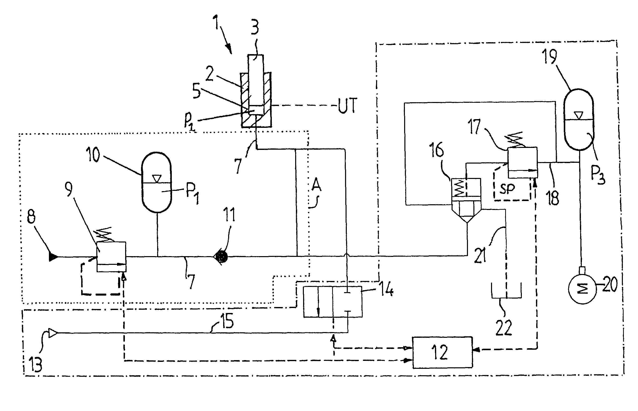
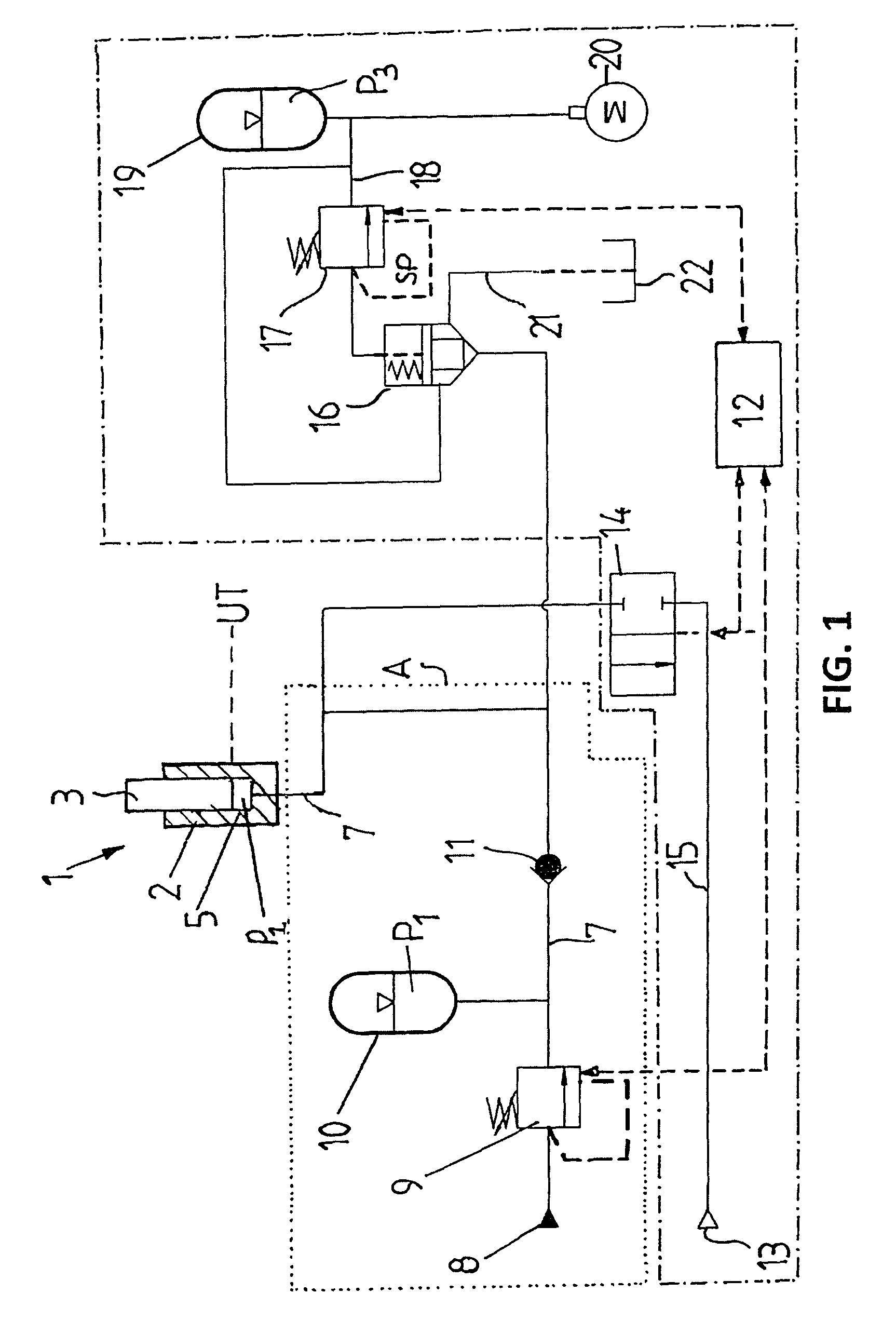
[0034]FIG. 1 shows the fundamental structure of the device according to the invention, which is to be used to apply the method according to the invention on a fineblanking press for the forming / fineblanking of parts. The cylinder / piston unit 1 is for example equipped with a piston 3 positioned in a counterforce cylinder 2. The working chamber 5 of the cylinder / piston unit 1 is connected to a low-pressure source 8 by a hydraulic line 7.

[0035]When looking from the low-pressure source 8, the hydraulic line 7 leads to the cylinder / piston unit 1 via a proportional pressure valve 9, a first accumulator 10 and a check valve 11. The proportional pressure valve 9 is also connected to a central control unit 12, which can be used to program the proportional pressure valve 9 to a corresponding cushion pressure P1. The piston 3 of the counterforce cylinder 2 in the press (not shown) is in rapid traverse, i.e. the piston is first moving from bottom dead centre UT towards top dead centre OT. The l...


PUM

PropertyMeasurementUnit
pressureaaaaaaaaaa
clamping forceaaaaaaaaaa
displacement pressureaaaaaaaaaa

Abstract

The cylinder / piston unit for a counterforce ram or vee ring of a fineblanking or stamping press equipped with at least one tool is continuously maintained at a preadjustable cushion pressure (P1) and is then subjected to a preadjustable displacement pressure (P2) from a connectable high-pressure source, with said pressure being set to a pressure (PU) varying between the cushion pressure (P1) and the pressure for forming or blanking by supplying a separate control oil quantity to a second accumulator via a central control unit, whereby a rise in pressure caused by the impact between the tool and the workpiece is regulated, independently of quantity of the control oil, from the pressure (P3) in the second accumulator to a permissible set pressure by discharging a significant part of the pressure pulse into a separate tank and the available cushion pressure allows ejection of the workpiece to be synchronized with retraction of the press ram.

Description

BACKGROUND OF THE INVENTION[0001]The invention relates to a method for controlling the synchronization of cylinder / piston units for counterforce rams and / or vee rings and for reducing pressure peaks during the fineblanking and / or forming of workpieces on a fineblanking or stamping press equipped with at least one tool, in which the cylinder / piston unit is subjected to the control pressure of a hydraulic fluid and the press ram is driven mechanically or hydraulically.[0002]The invention further relates to a device for controlling a piston / cylinder unit for the counterforce ram and vee ring and for reducing pressure peaks during the fineblanking of workpieces for implementation of the method with a fineblanking or stamping press, which is equipped with at least one tool consisting of an upper section and a lower section, which is allocated at least one piston / cylinder unit of the press for at least one counterforce ram and / or vee ring of the tool in addition to one press ram, and with...

Claims


Application Information

Patent Timeline
Patent Type & Authority Patents(United States)
IPC IPC(8): B21J7/14B21J9/18
CPCB21D24/14B21D28/16B21D28/20F15B1/024F15B2211/212F15B2211/50518F15B2211/625B30B15/16B30B15/18B30B15/22B30B15/26
Inventor SCHALTEGGER, MARKUSWINKLER, THOMASJUHASZ, FRANCOIS
Owner FEINTOOL INT HLDG
Why Eureka
Try Eureka