Twin beam charged particle column and method of operating thereof

a charged particle and twin beam technology, applied in the direction of material analysis using wave/particle radiation, instruments, nuclear engineering, etc., can solve the problems of serious problems, introduction of aberrations, and inability to charge particles,

Active Publication Date: 2013-02-19
ICT INTEGRATED CIRCUIT TESTING GESELLSCHAFT FUER HALBLEITERPRUEFTECHNIK GMBH
View PDF23 Cites 61 Cited by
  • Summary
  • Abstract
  • Description
  • Claims
  • Application Information

AI Technical Summary

Problems solved by technology

However, the inspection of wafers or masks for defects requires the examination of the whole wafer or mask area.
However, using a single beam at high resolution can result in a throughput limitation.
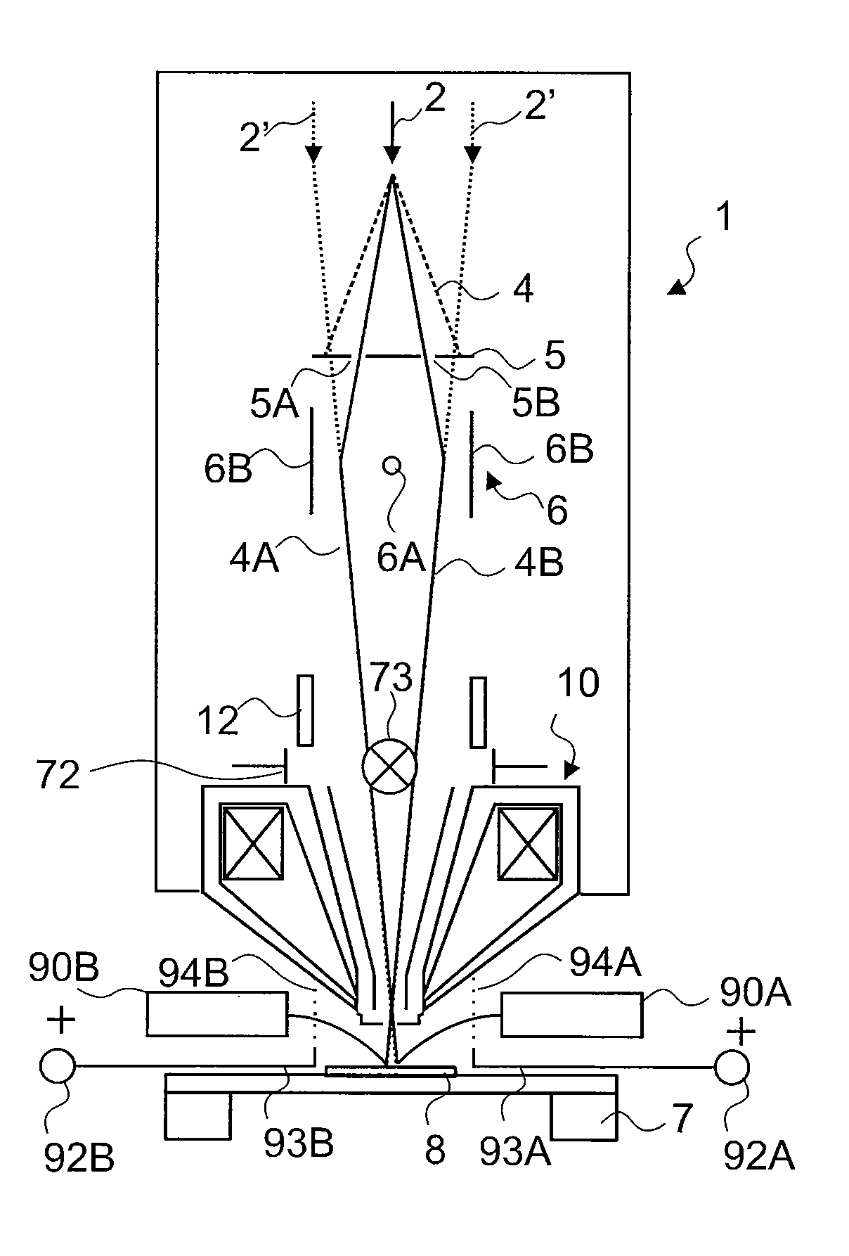
Thereby, the introduction of aberrations due to having multiple beams in one column, typically on different axes, is a serious issue to be considered.

Method used


Image

  • Twin beam charged particle column and method of operating thereof
  • Twin beam charged particle column and method of operating thereof
  • Twin beam charged particle column and method of operating thereof

Examples


Embodiment Construction

[0027]Reference will now be made in detail to the various embodiments of the invention, one or more examples of which are illustrated in the figures. Each example is provided by way of explanation of the invention and is not meant as a limitation of the invention. For example, features illustrated or described as part of one embodiment can be used on or in conjunction with other embodiments to yield yet a further embodiment. It is intended that the present invention includes such modifications and variations.

[0028]Without limiting the scope of protection of the present application, in the following description the charged particle beam device or components thereof will exemplarily be referred to as a charged particle beam device including the detection of secondary electrons. The present invention can still be applied for apparatuses and components detecting corpuscles such as secondary and / or backscattered charged particles in the form of electrons or ions, photons, X-rays or other...


PUM


Abstract

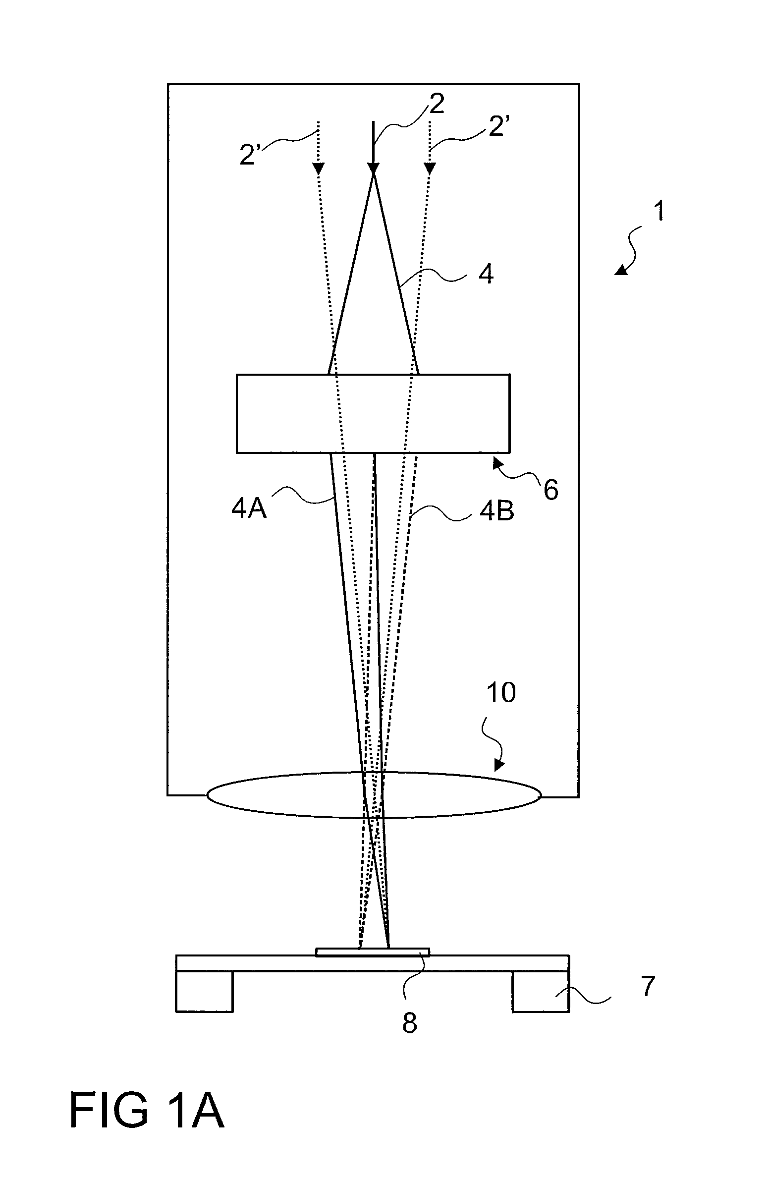
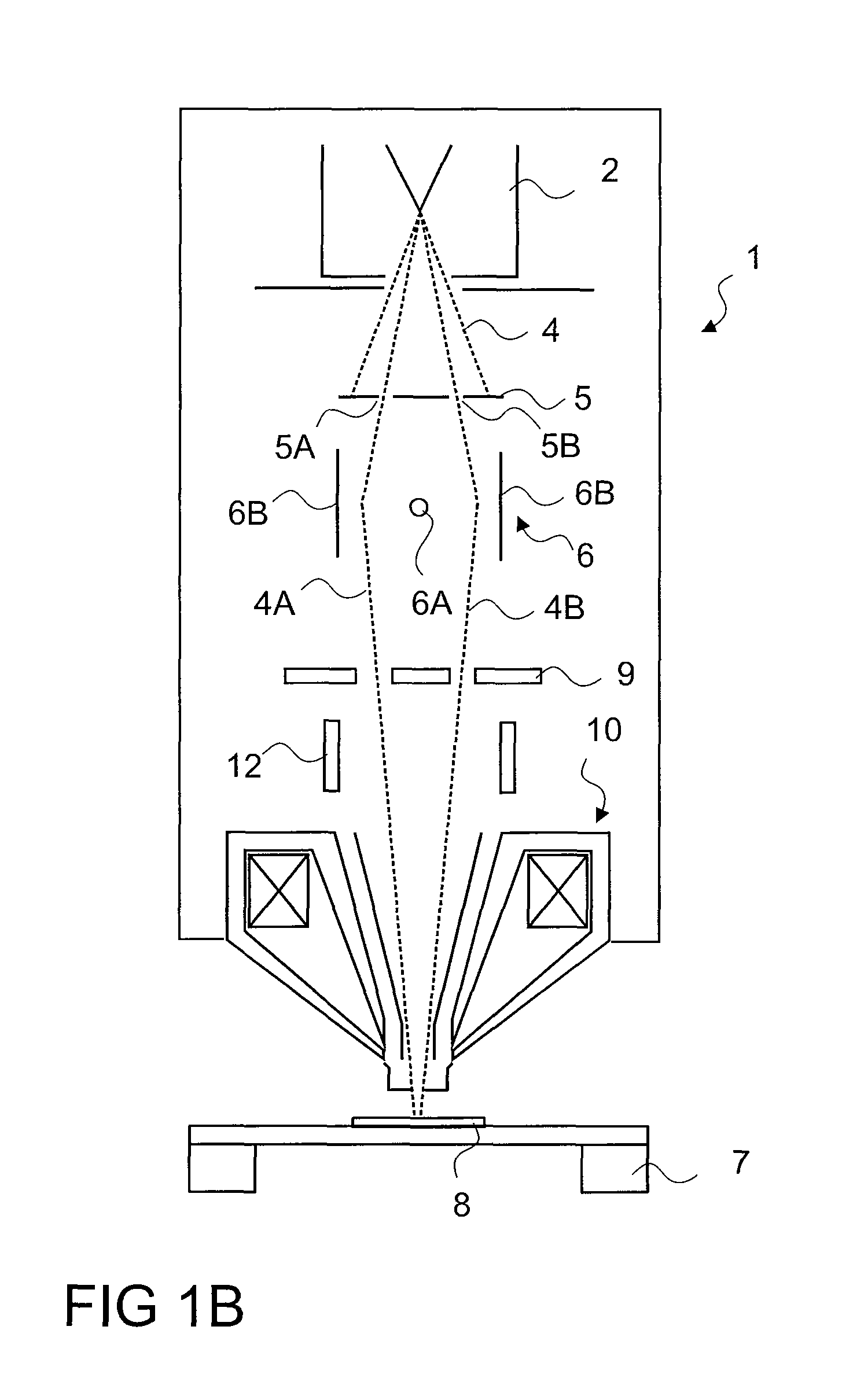
A column for a charged particle beam device is described. The column includes a charged particle emitter for emitting a primary charged particle beam as one source of the primary charged particle beam; a biprism adapted for acting on the primary charged particle beam so that two virtual sources are generated; and a charged particle beam optics adapted to focus the charged particle beam simultaneously on two positions of a specimen corresponding to images of the two virtual sources.

Description

FIELD OF THE INVENTION[0001]Embodiments of the invention relate to a charged particle beam apparatus and methods of operating thereof. In particular, they relate to an apparatus with two beams of charged particles per charged particle beam column and a method of generating two charged particle beams per column.BACKGROUND OF THE INVENTION[0002]Technologies such as microelectronics, micromechanics and biotechnology have created a high demand for structuring and probing specimens within the nanometer scale. Micrometer and nanometer scale process control, inspection or structuring, is often done with charged particle beams. Probing or structuring is often performed with charged particle beams which are generated and focused in charged particle beam devices. Examples of charged particle beam devices are electron microscopes, electron beam pattern generators, ion microscopes as well as ion beam pattern generators. Charged particle beams, in particular ion beams, offer superior spatial res...

Claims


Application Information

Patent Timeline
Patent Type & Authority Patents(United States)
IPC IPC(8): G01B15/00
CPCH01J37/147H01J37/1471H01J37/244H01J37/28H01J2237/0453H01J2237/04756H01J2237/1514H01J2237/153H01J2237/24465H01J2237/24592H01J2237/2817
Inventor FROSIEN, JURGEN
Owner ICT INTEGRATED CIRCUIT TESTING GESELLSCHAFT FUER HALBLEITERPRUEFTECHNIK GMBH
Why Eureka
Try Eureka