
Tilting actuator with close-gap electrodes

a technology of close gap electrodes and actuators, applied in the field of electromechanical transducing and actuating, can solve the problem of overcompensation of the tendency of electrodes to increase their overlap upon application of voltage bias

Inactive Publication Date: 2013-02-19
RAMOT AT TEL AVIV UNIV LTD
View PDF28 Cites 5 Cited by
  • Summary
  • Abstract
  • Description
  • Claims
  • Application Information

AI Technical Summary

Benefits of technology

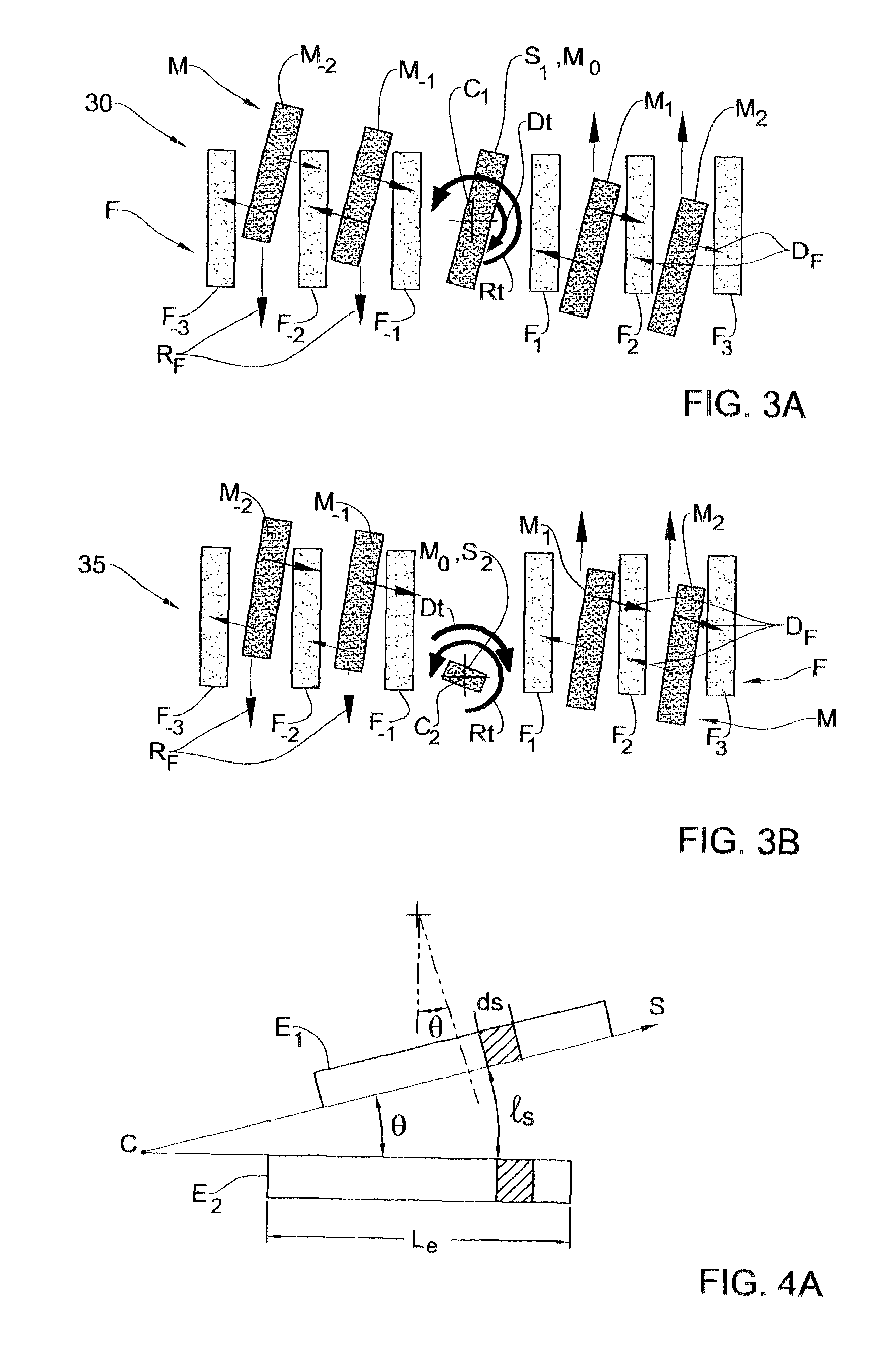
This patent describes an electromechanical tilting device that can overcome limitations in frequency and control the oscillation range more precisely. The device has interdigitated electrodes and a suspension that causes changes in the overlapping regions of the electrodes to make the device more efficient. The method is also discussed. The technical effects of this patent are improved control over the tilt movement and efficiency of the tilting device.

Problems solved by technology

In the technique of the inventors, however, the tendency of electrodes to increase their overlap upon an application of voltage bias can be overcompensated by the tendency of electrodes to move closer to each other.

Method used


Image

  • Tilting actuator with close-gap electrodes
  • Tilting actuator with close-gap electrodes
  • Tilting actuator with close-gap electrodes

Examples


Embodiment Construction

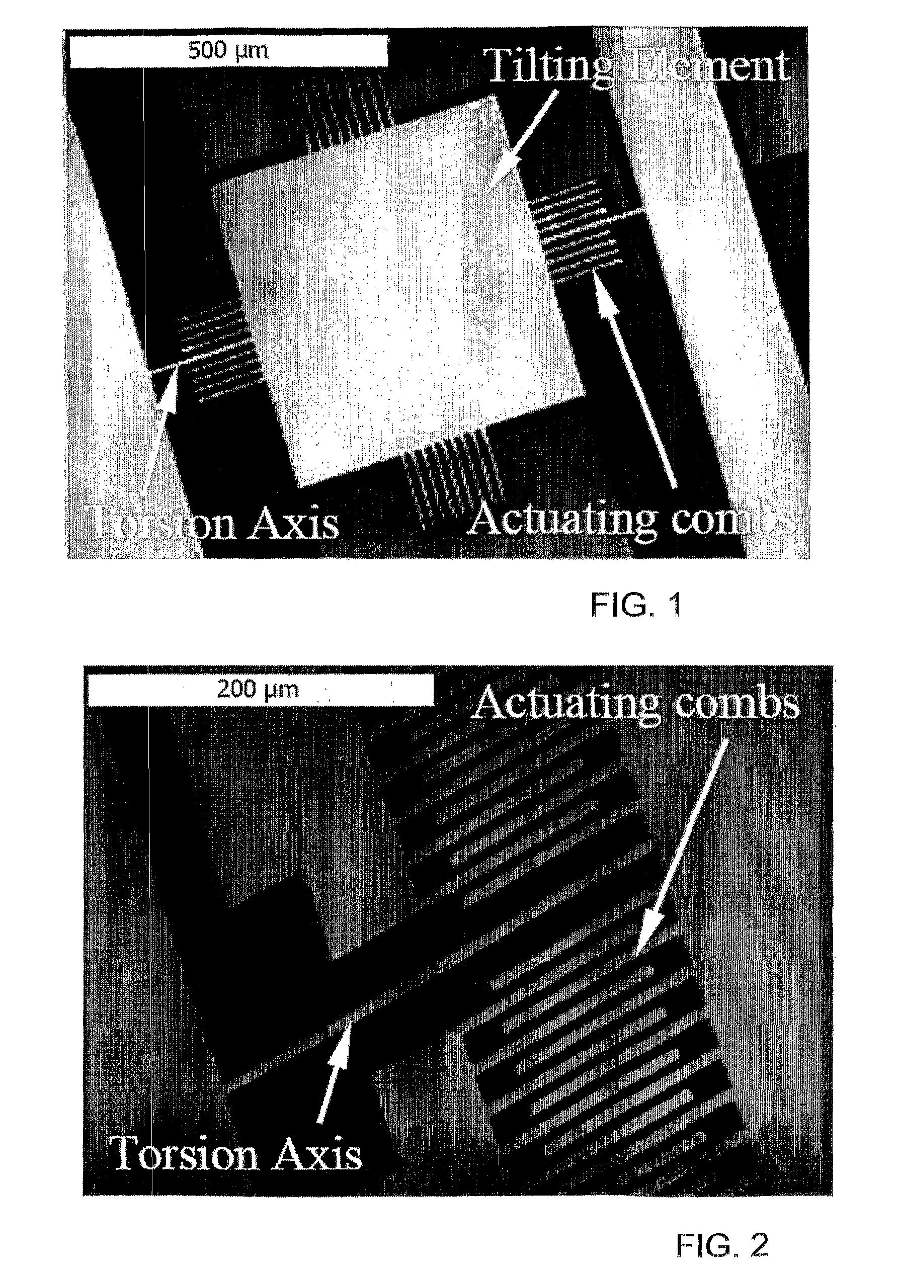
[0079]Referring to FIG. 1, there is shown a scanning electron microscopy (SEM) micrograph of an electromechanical tilting device fabricated by the inventors according to their technique. The scale bar in the upper left corner of the figure corresponds to 500 μm. The device incorporates a tilting element suspended from two sides using an elastic torsion axis and an array of comb-like high aspect ratio electrode structures oriented in a direction parallel to a rotation axis (defined by the torsion axis). The fingers of combs being on the same side of the tilting element are interdigitated. The combs are made from a single structural layer. Electrically, in this example, fingers (or teeth) of the same comb form a single electrode, but it is convenient to refer to each finger as to a separate electrode for electrical torque calculation and because the fingers of the same comb can be made electrically isolated. Comb-like electrode structures appear also at the upper and lower edges of th...


PUM


Abstract

An electromechanical tilting device including a first and a second electrode structures, shaped, positioned and oriented to define at least partially interdigitated electrodes, and a suspension defining a tilt-containing motion path for the second structure with respect to the first structure. The motion path is selected to cause changes in overlapping regions and overlapping regions' gaps of the interdigitated electrodes. The device is configured such that an increase in one or more voltage bias applied to interdigitated driving electrodes makes a decrease in a total area of overlapping regions of the driving electrodes electrically energetically favorable.

Description

RELATED APPLICATIONS[0001]This application is a Continuation of International Application No. PCT / IL2007 / 001554, filed on Dec. 16, 2007, which in turn claims the benefit under 35 USC 119(e) of U.S. Provisional Application No. 60 / 874,675, filed on Dec. 14, 2006, both of which are incorporated herein by reference in their entirety.FIELD OF THE INVENTION[0002]This invention relates to electromechanical transducing and actuating in general and to tilt MEMS actuating in variants.BACKGROUND OF THE INVENTIONReferences[0003][1] D. Lee, U. Krishnamoorthy, K. Yu, and O. Solgaard, “Single-crystalline silicon micromirrors actuated by self-aligned vertical electrostatic combdrives with piston-motion and rotation capability,” Sensors and Actuators A, vol. 114, pp. 423-428, 2004;[0004][2] K. Isamoto, K. Kato, A. Morosava, C. Chong, H. Fujita and H. Toshiyoshi, “A 5-V operated MEMS variable optical attenuator by SOI bulk micromachining,” IEEE J. of Selected Topics in Quantum Electronics, vol. 10, p...

Claims


Application Information

Patent Timeline
Patent Type & Authority Patents(United States)
IPC IPC(8): B81B5/00B81B7/02
CPCB81B3/0021H02N1/008H02N1/006G02B26/0841B81B3/0018
Inventor KRYLOV, SLAVASHMILOVICH, TSVI
Owner RAMOT AT TEL AVIV UNIV LTD
Learn More