Apparatus for measuring thin film refractive index and thickness with a spectrophotometer

a thin film refractive index and spectrophotometer technology, applied in the direction of optical radiation measurement, instruments, spectrometry/spectrophotometry/monochromators, etc., can solve the problems of difficult to measure the thickness and the index individually, the thickness and the index are not very accurate, and the cost of prism couplers and ellipsometers are quite high and other problems, to achieve the effect of improving the accuracy of the devi

Inactive Publication Date: 2013-02-19
STREATER ALAN DOUGLAS
View PDF6 Cites 8 Cited by
  • Summary
  • Abstract
  • Description
  • Claims
  • Application Information

AI Technical Summary

Benefits of technology

[0009]Some embodiments include polarizers for spectrophotometers that are not already polarized. Other embodiment...

Problems solved by technology

This method has the advantage that it is applicable to all wavelengths accessible to the spectrophotometer, but it has the disadvantage that it is traditionally not very accurate.
Prism couplers and Ellipsometers are quite expensive and are usually more limited in the range of wavelengths over which the index can be measured.
The difficulty with measuring the index of refraction for thin film materials from a transmission scan is that the gross features in the transmission spectrum are largely dependent on only the optical thickness, which is the product of the index and the thickness, but the gross ...

Method used


Image

  • Apparatus for measuring thin film refractive index and thickness with a spectrophotometer
  • Apparatus for measuring thin film refractive index and thickness with a spectrophotometer
  • Apparatus for measuring thin film refractive index and thickness with a spectrophotometer

Examples


first embodiment

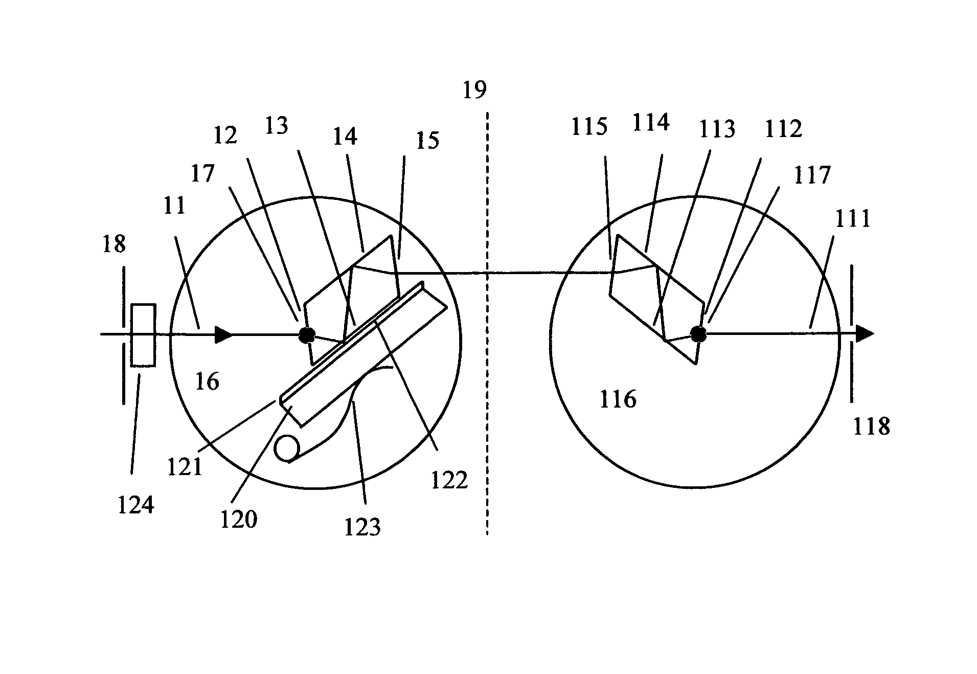
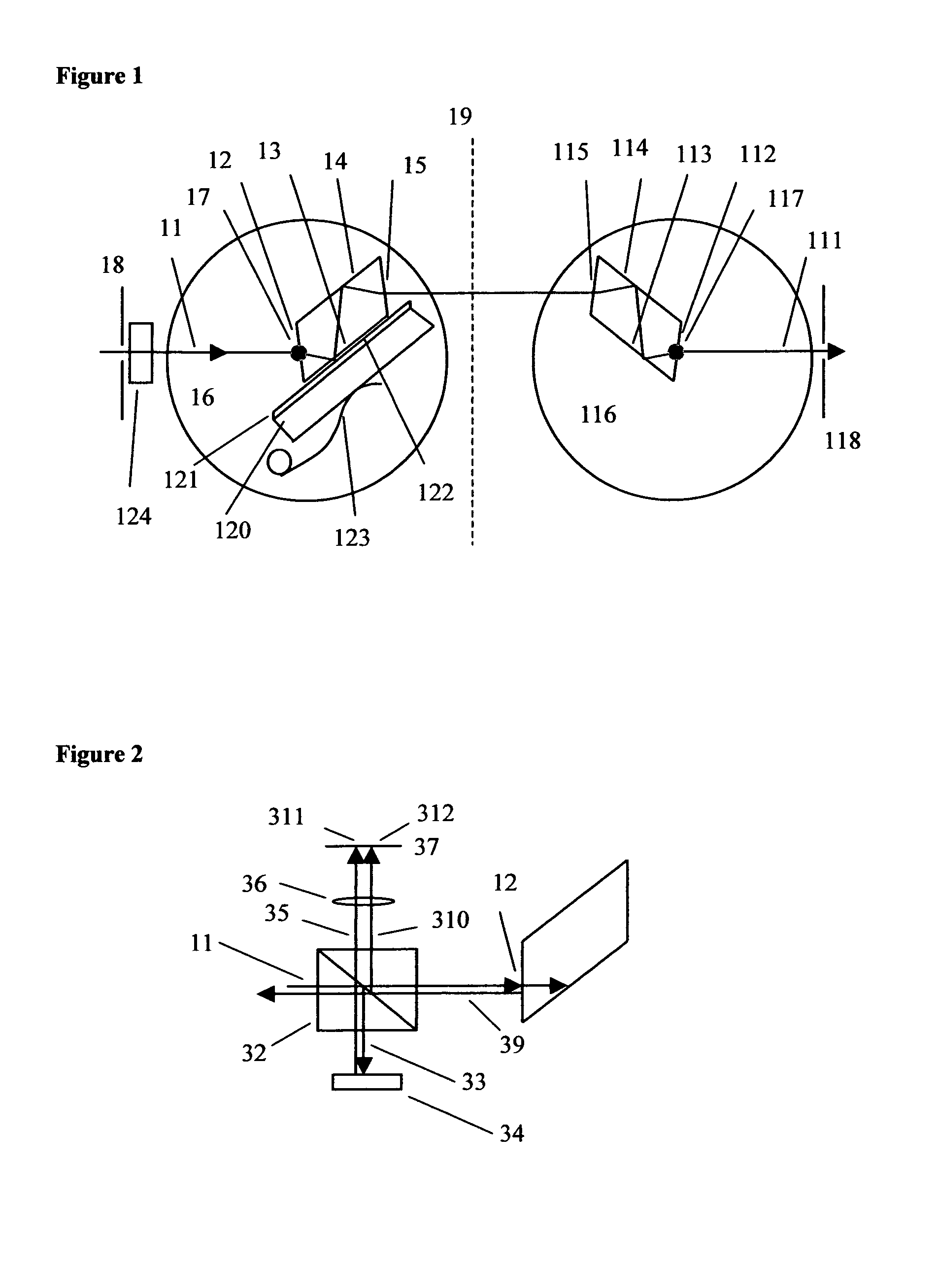
[0023]a device for measuring the refractive index and thickness of a thin film that is applied to a sample plate is shown schematically in FIG. 1.

[0024]An input beam path 11 represents a path that electromagnetic radiation of a central wavelength and direction enters the device. The beam path has the form of a line in space with a direction.

[0025]A first right prism consists of material that has a refractive index and that is transparent in the first wavelength band, and has a refractive index np. The first right prism has at least four surfaces with normals that all lie in a plane, which in the claims we list as:

[0026]A first planar first transmission surface 12

[0027]A first planar first reflection surface 13, which forms an acute angle with the first planar first transmission surface that we call the first prism angle

[0028]A first planar second transmission surface 14, that is parallel to the first planar first transmission surface

[0029]A first planar second reflection surface 15,...

case 1

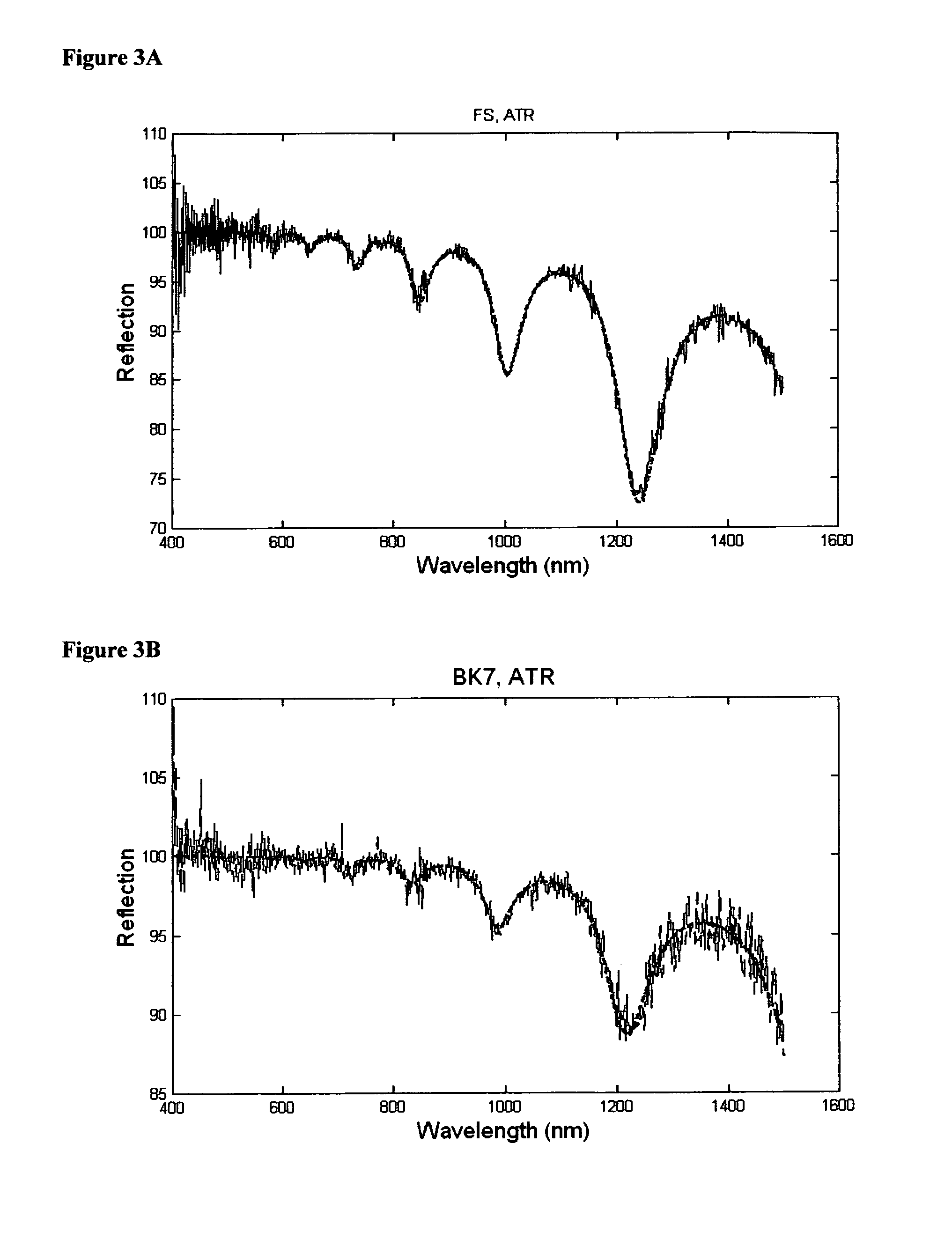
[0055 is the more difficult case to treat theoretically, so we start with case 2. For case 2, in which light can be transmitted through the sample plate, the transmission provides an energy loss mechanism. Except in extraordinary circumstances, the propagation length will be much smaller than the beam diameter, and an infinite plane wave solution will be valid, so we can use standard thin film modeling to calculate the reflection and transmission of the system. This theory is described, for example, in Thin-Film Optical Filters, Fourth Edition, Taylor & Francis (CRC Press) (2010), by A. Macleod.

[0056]Case 1 is more difficult theoretically because plane wave theory does not apply directly. An infinite plane wave will couple into and out of the waveguide mode periodically, always resulting in 100% reflection. There are several physical effects, however that can reduce the reflection to values that are less than 100%. The first mechanism is loss due to scattering and absorption in the ...


PUM


Abstract

A device is provided that can be inserted into a spectrophotometer, in order to measure the thickness and refractive index of a thin film that is on a sample plate. A pair of identical parallelogram prisms diverts the spectrophotometer beam to measure the attenuated total reflection, and returns an output beam that is in the original beam path, independent of wavelength and rotation angle. The attenuated total reflection of the thin film sample plate is measured in a prism coupling geometry, as a function of wavelength and angle. From this data, combined with normal incidence transmission data, the thickness and refractive index can be extracted.

Description

CLAIM OF PRIORITY[0001]This patent application claims priority under 35 USC 119(e)(1) from U.S. Provisional Patent Application Ser. No. 61 / 338,227 filed Feb. 16, 2010 of common inventorship herewith entitled Apparatus and method for accurately measuring thin film index and thickness with a spectrophotometer.BACKGROUND OF THE INVENTION[0002]This invention relates to an apparatus and method for measuring the thickness of a thin film layer on a sample plate, and measuring the refractive index of the material of the thin film layer as a function of wavelength.[0003]The optical properties of thin films are often sensitive to the process used for producing the film. For example in thin film deposition the index of refraction is often sensitive to partial pressures of process gases, beam voltages, substrate temperatures, and a host of other parameters, some of which are not even well known or understood. Complex multi-layer thin film designs require accurate knowledge of the optical proper...

Claims


Application Information

Patent Timeline
IPC IPC(8): G01B11/28
CPCG01B11/0633G01N21/552G01N21/8422
Inventor STREATER, ALAN DOUGLAS
Owner STREATER ALAN DOUGLAS
Why Eureka
Try Eureka