
Preform for stretch blow-molded bottle

a bottle and preform technology, applied in the field of closed-dense preforms, can solve the problems of increasing the amount of stretching, the bottle bottom section is thin, and the bottle bottom section has a large thickness, so as to reduce the weight of the bottle bottom surface section, improve the efficiency of stretching the bottom section of the preform, and increase the thickness of the bottom section

Active Publication Date: 2013-03-05
A K TECH LAB INC
View PDF9 Cites 3 Cited by
  • Summary
  • Abstract
  • Description
  • Claims
  • Application Information

AI Technical Summary

Benefits of technology

The preform design facilitates uniform stretching, reducing the weight of the bottle's bottom surface section while maintaining sufficient thickness for durability, and prevents the undercut problem, allowing for efficient mold release and reduced resin excess.

Problems solved by technology

The barrel section tends to be thin because the amount of stretching increases due to the delay of the stretching of the bottom section.
However, the bottom surface section of the bottle has a large thickness due to the excess resin.
However, it is not easy to reduce the thickness of the bottom section to the extent that contributes to the reduction in weight of the bottom surface section of the bottle.
The reason that the bottom surface section of the bottle formed by stretch blow molding of the preform is thicker than the barrel section is insufficient stretching in the axial direction caused by internal temperature difference due to the thickness distribution and by the delay of stretching in the bottom section.
However, to form a preform such that the bottom section is thicker than the barrel section, an undercut must be provided in the bottom section of the mold structure, and the preform cannot be released from the cavity of such a mold and a core mold by drawing.
Moreover, another problem arises in that the thickness of the outer circumference of the bottom edge of the formed bottle can be non-uniform due to the reduction in thickness of the bent portion by stretching.

Method used


Image

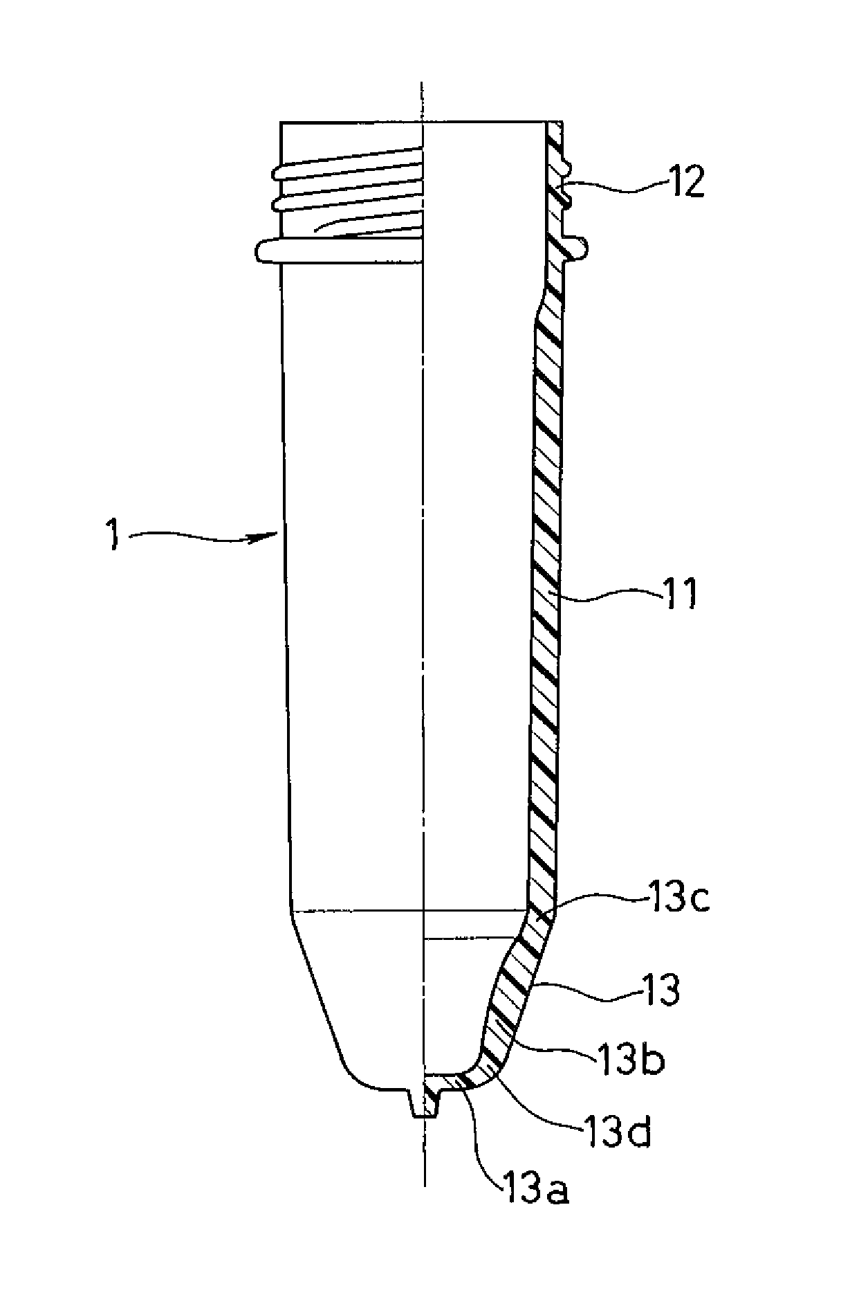
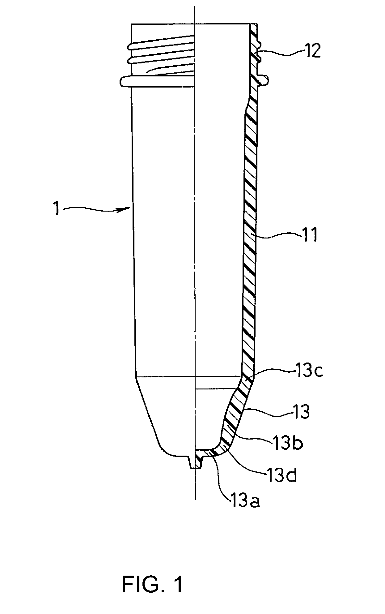
  • Preform for stretch blow-molded bottle
  • Preform for stretch blow-molded bottle
  • Preform for stretch blow-molded bottle

Examples


example

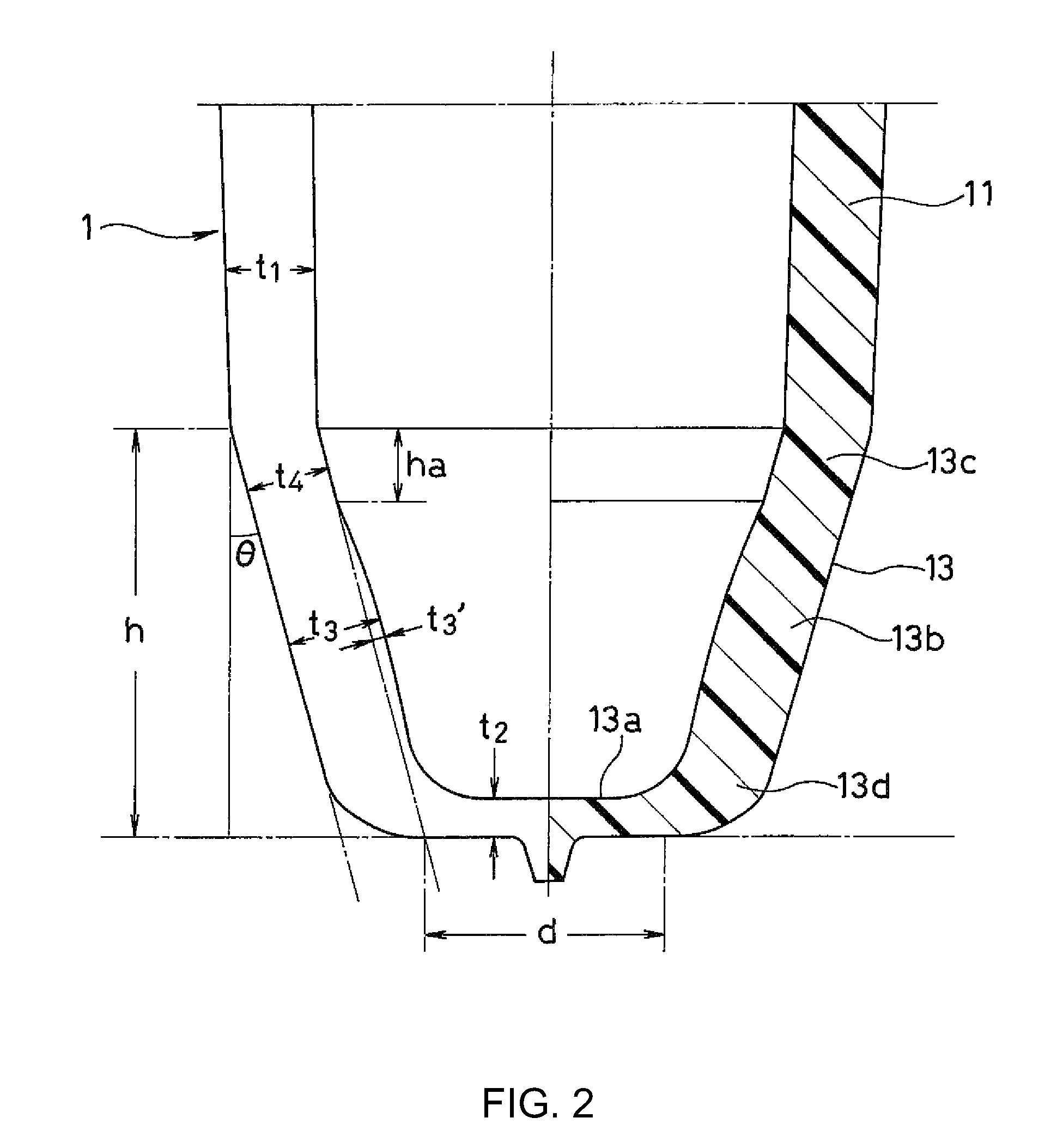
Preform (Resin Material: Polyethylene Terephthalate, Weight: 50 g)

[0048]Thickness (Set Values)

[0049]

Central portion of barrel section (t1)3.55 mmBottom surface central portion (t2)1.72 mmBottle bottom surface-forming portion (t3)3.85 mmBottle bottom edge-forming portion (t4)3.45 mmHeight:Barrel section82 mmBottom section (h)18 mm

[0050]Diameter

[0051]

Inner diameter of central portion of barrel section (D)27.2 mmBottom surface central portion (d)15.7 mmInclination angle of bottom section (θ)11.8°

[0052]Stretch Blow Molding Temperature (Temperature (° C.) of Outer Surface 5 Seconds after Removal from Mold)

[0053]

Central portion of barrel section (t1)101.4Bottle bottom surface-forming portion (t3)105.4Bottle bottom edge-forming portion (t4)99.6


PUM

PropertyMeasurementUnit
thickness t2aaaaaaaaaa
Weightaaaaaaaaaa
diameteraaaaaaaaaa

Abstract

A preform having an inverted truncated conical bottom section is used. The inclined inner surface of a bottle bottom surface-forming portion of the bottom section is formed into a gently curved convex surface that extends from the lower portion of a bottle bottom edge-forming portion of the bottom section to a curved portion in the lower portion of the bottom section so that the thickness of the bottle bottom surface-forming portion is greater than the thickness of the barrel section of the preform and the thickness of the bottle bottom edge-forming portion. The increase in thickness of the bottom section improves the efficiency of stretching the bottom section, and the circumferential wall of the bottom section can thereby be efficiently stretched. This allows a reduction in weight (thickness) of the bottom surface section of a stretch blow molded bottle, and a reduction in weight of the bottle is thereby achieved.

Description

BACKGROUND OF THE INVENTION[0001]1. Field of the Invention[0002]The present invention relates to a closed-end preform that is formed by injection molding of a plastic material, used to form a bottle by stretch blow molding without reheating, and can reduce the weight of the bottle.[0003]2. Description of the Related Art[0004]Examples of the stretch blow molding of plastic materials such as polyethylene terephthalate, polycarbonate, and the like into a bottle include: the cold parison method in which a closed-end preform is injection-molded in a mold, cooled, solidified, and released from the mold, and then reheated to a molding temperature, before it is stretch blow molded into a bottle; and the hot parison method in which a preform in a high-temperature state with its inside not completely cooled and having high internal heat is released from a mold and then stretch blow molded into a bottle while the high-temperature state is maintained (U.S. Pat. No. 5,364,585).[0005]In the hot p...

Claims


Application Information

Patent Timeline
Patent Type & Authority Patents(United States)
IPC IPC(8): B32B1/08B32B23/00
CPCB29B11/14B29B11/08Y10T428/139B29B2911/1402B29B2911/14026B29B2911/14033B29B2911/1404B29B2911/14106B29B2911/14133B29B2911/1444B29B2911/14486B29B2911/14633B29B2911/1464B29B2911/14693B29B2911/147B29B2911/14753B29B2911/1476B29B2911/14826B29B2911/1498B29C49/06B29K2067/00B29K2105/258B29L2031/7158Y10T428/13Y10T428/1352Y10T428/1359Y10T428/1303B29C2949/3024B29C2949/24B29C2949/26B29C2949/28B29C2949/22B29C2949/3032B29C2949/0724B29C2949/0733B29C2949/078B29C2949/0818B29C2949/0817B29C2949/0826B29C2949/0827B29C2949/0773B29C2949/0835B29C2949/0836B29C2949/0846B29C2949/0872B29C49/071B29C2949/0715
Inventor YANAGIMACHI, YUKIO
Owner A K TECH LAB INC
Learn More