
Method for regulating a welding current source and welding current source for carrying out the method

a technology of welding current source and welding electrode, which is applied in the direction of welding apparatus, arc welding apparatus, manufacturing tools, etc., can solve the problems of relatively high cost of use of transducer based on hall principle, and increase the welding current flowing from the welding electrode to the workpiece, so as to improve the regulation of welding current and low cost

Inactive Publication Date: 2013-03-05
LORCH SCHWEISSTECHNIK GMBH
View PDF10 Cites 2 Cited by
  • Summary
  • Abstract
  • Description
  • Claims
  • Application Information

AI Technical Summary

Benefits of technology

This approach allows for cost-effective and low-power regulation of the welding current, effectively managing arc resistance and preventing spatter by adjusting the primary current, thereby achieving improved welding behavior.

Problems solved by technology

The transfer of the drops may lead to the formation of a short circuit between the welding electrode and the workpiece, with the result that the welding current flowing from the welding electrode to the workpiece increases very strongly.
The use of a shunt involves a not inconsiderable power loss and the use of a transducer based on the Hall principle is relatively expensive.

Method used


Image

  • Method for regulating a welding current source and welding current source for carrying out the method
  • Method for regulating a welding current source and welding current source for carrying out the method
  • Method for regulating a welding current source and welding current source for carrying out the method

Examples


Embodiment Construction

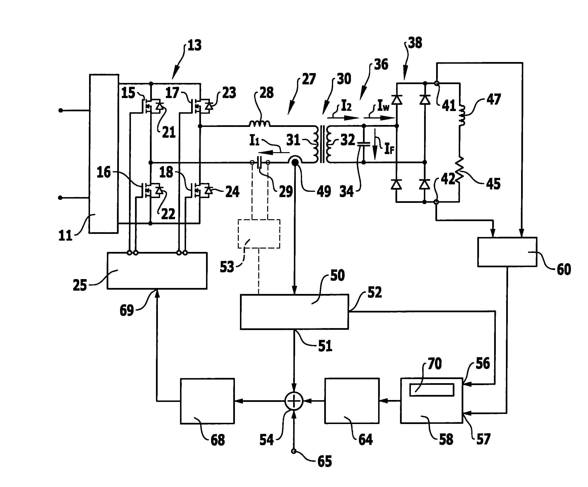
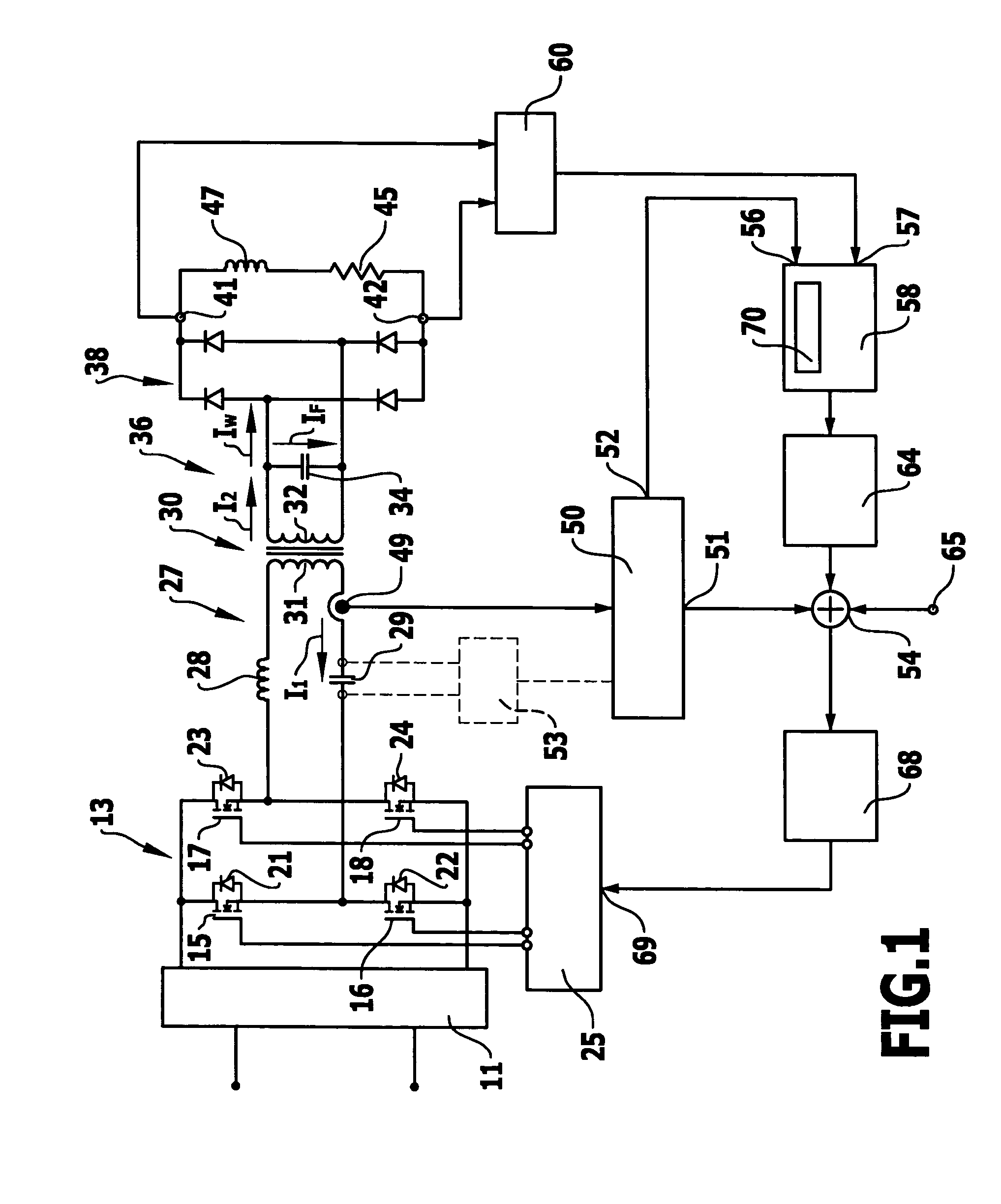
[0033]In FIG. 1, a simplified block diagram of a welding current source according to the invention is schematically represented. This welding current source comprises a rectifier 11 on the input side, which is adapted to be connected in a manner that is customary and not apparent from the drawing to a power supply network, in particular to a public power supply network, such as for example an alternating voltage network with 230 V or 400 V. In the rectifier 11 on the input side, the alternating voltage provided by the power supply network is rectified.

[0034]The rectifier 11 on the input side is connected to a bridge circuit 13 and supplies it with direct current voltage. In the exemplary embodiment represented, the bridge circuit 13 is formed as a full bridge and has four switching elements 15, 16, 17, 18 with associated freewheeling diodes 21, 22, 23, 24. Bridge circuits 13 of this kind are known per se to a person skilled in the art and therefore need no further explanation here. ...


PUM

PropertyMeasurementUnit
resistanceaaaaaaaaaa
phase angleaaaaaaaaaa

Abstract

The invention relates to a method for regulating a welding current source with a current transformer, which has a series resonant circuit on the primary side and a parallel resonant circuit on the secondary side, the series resonant circuit being supplied with a variable alternating voltage by a bridge circuit and the parallel resonant circuit providing energy to a welding process by way of a rectifier, and a control unit controlling the bridge circuit in dependence on at least one state variable of the welding current source. In order to develop the method in such a way as to make regulation possible at low cost and with as little power loss as possible, it is proposed according to the invention that only the primary current or a state variable on the primary side corresponding to the primary current is recorded as the electrical-current state variable of the welding current source and a control signal dependent on the primary current or on the state variable corresponding thereto is fed to the control unit. A welding current source for carrying out the method is also proposed.

Description

[0001]The present disclosure relates to the subject matter disclosed in German application number 10 2009 008 199.2 of Feb. 4, 2009, which is incorporated herein by reference in its entirety and for all purposes.BACKGROUND OF THE INVENTION[0002]The invention relates to a method for regulating a welding current source with a current transformer, which has a series resonant circuit on the primary side and a parallel resonant circuit on the secondary side, the series resonant circuit being supplied with a variable alternating voltage by a bridge circuit and the parallel resonant circuit providing energy to a welding process by way of a rectifier, and a control unit controlling the bridge circuit in dependence on at least one state variable of the welding current source.[0003]The invention also relates to a welding current source for carrying out the method.[0004]Arc welding methods, in which an arc burns between a welding electrode and a workpiece, are known in various configurations. ...

Claims


Application Information

Patent Timeline
Patent Type & Authority Patents(United States)
IPC IPC(8): B23K9/10
CPCB23K9/0956
Inventor AIGNER, HUBERT
Owner LORCH SCHWEISSTECHNIK GMBH
Learn More