Narrow band RF filter circuits, devices and processes using impedance translation

a filter circuit and narrow band technology, applied in the field of active filters, can solve the problems of inability to reliably achieve the effect of auxiliary path mixer circuits to handle interferences, and the expense of auxiliary path mixer circuits

Active Publication Date: 2013-03-05
TEXAS INSTR INC
View PDF8 Cites 8 Cited by
  • Summary
  • Abstract
  • Description
  • Claims
  • Application Information

AI Technical Summary

Problems solved by technology

That approach introduces the expense of auxiliary path mixer circuits to handle the interferer, and the additional hardware and extra noise introduced by the auxiliary path may not be insignificant.
Starting from a Q on the order of 10 for on-chip LC, it is believed not practical or economical to achieve this reliably.

Method used


Image

  • Narrow band RF filter circuits, devices and processes using impedance translation
  • Narrow band RF filter circuits, devices and processes using impedance translation
  • Narrow band RF filter circuits, devices and processes using impedance translation

Examples


Embodiment Construction

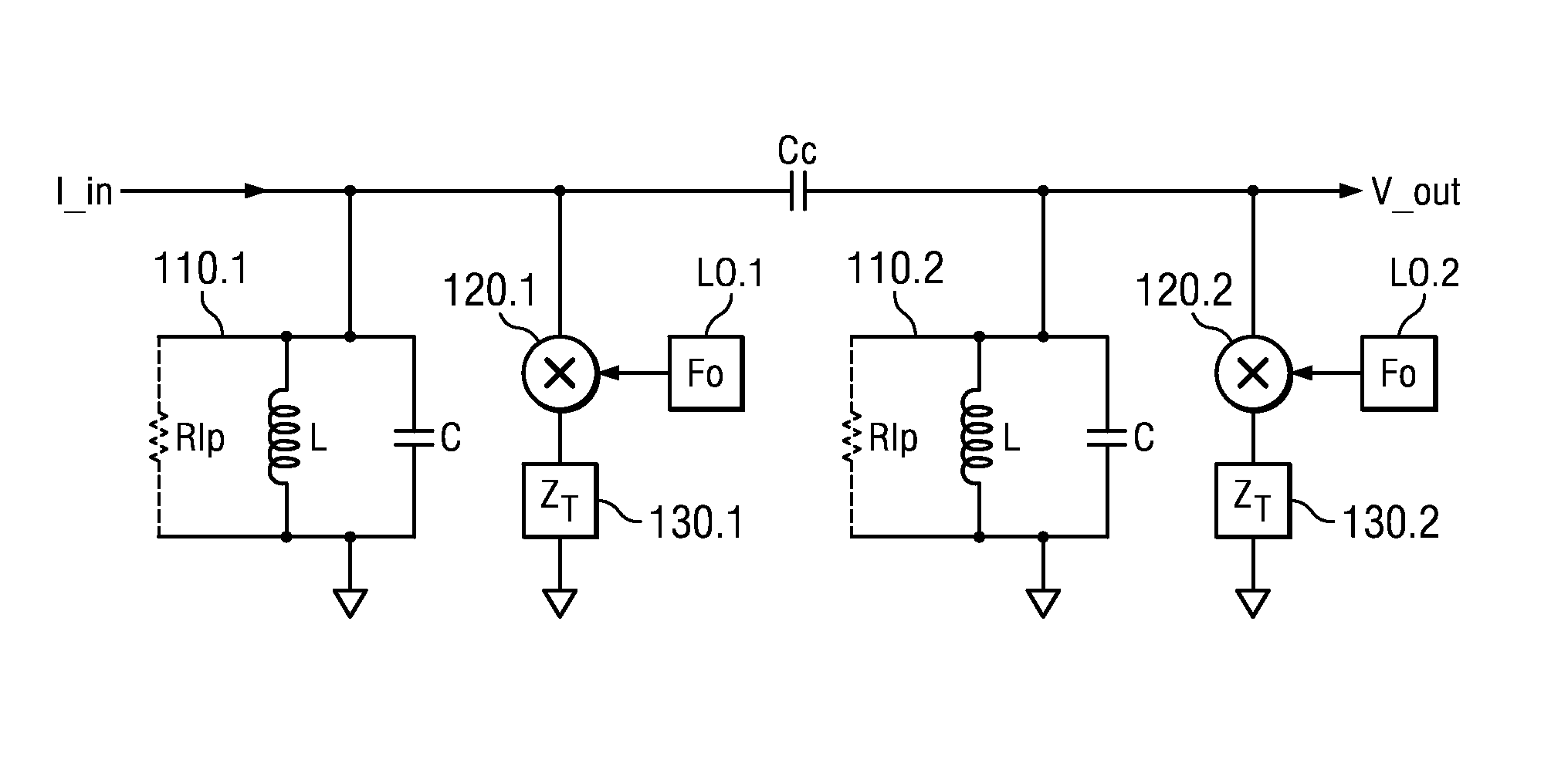
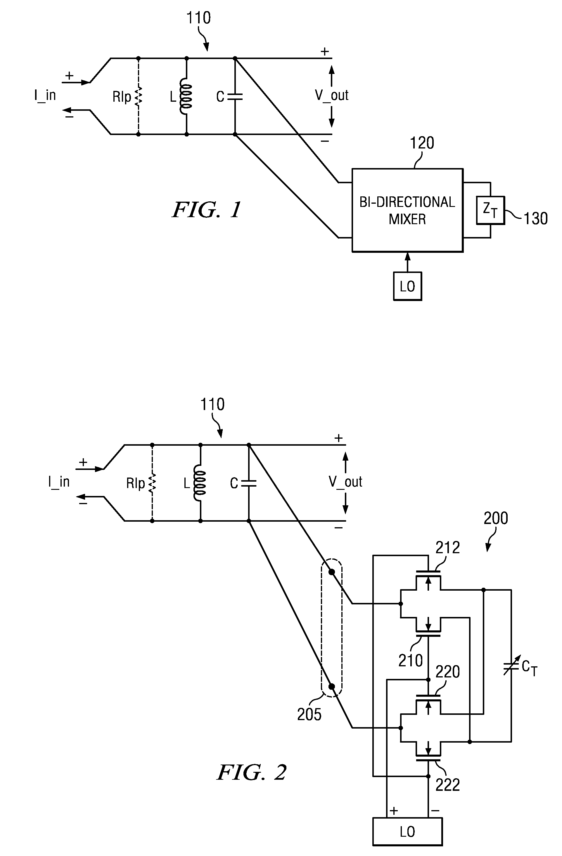
[0033]In FIG. 1, an LC filter circuit 110 at RF signal frequency is augmented with a single bi-directional mixer 120 coupled across the output of the LC filter circuit for conversion to baseband and back. The bi-directional mixer 120 is terminated in a baseband filter impedance ZT (130). High reverse isolation is neither necessary nor particularly desirable in this embodiment. The bi-directionality reflects the filter impedance ZT 130 from baseband to the RF signal frequency band with low noise, low cost and little constraint on mixer 120 isolation.

[0034]In the embodiments of FIGS. 1 and 2, a tuned LC filter 110 is used to improve the selectivity of receive operations and also provide filtering for transmit signal paths. In FIG. 2, a one-port network is implemented by using a bi-directional mixer 200 and an appropriate termination is connected to the tuned LC filter 110. In this way an active filter circuit is provided having a parallel inductor L and capacitance C for wireless freq...


PUM


Abstract

An active filter circuit includes an inductance-capacitance (LC) circuit (110) for wireless frequency input, a bi-directional mixer (120) and a filter impedance (130) series-coupled across at least part of the LC circuit (110), and another mixer (420) coupled to at least some portion of the LC circuit. Other circuits, processes, receivers, transmitters and transceivers are disclosed.

Description

CROSS-REFERENCES TO RELATED APPLICATIONS[0001]This application is related to India Patent Application 468 / CHE / 2010 “Narrow Band RF Filter Circuits, Devices and Processes Using Impedance Translation,” filed Feb. 23, 2010, for which priority is claimed under the Paris Convention and 35 U.S.C. 119 and all other applicable law, and which is incorporated herein by reference in its entirety.[0002]This application incorporates herein the following U.S. patent application Publication by reference in its entirety: 20090289721, Rajendran et al., Nov. 26, 2009 (TI-66109) filed May 5, 2009, titled “Circuits, Processes, Devices and Systems for Full Integration of RF Front End Module Including RF Power Amplifier.”[0003]This application incorporates herein the following U.S. patent application Publication by reference in its entirety: 20100027568 Rajendran et al., Feb. 4, 2010 (TI-65587) filed Jul. 29, 2008, titled “Technique for Sharing Transmit and Receive Ports of a CMOS Based Transceiver.”STAT...

Claims


Application Information

Patent Timeline
Patent Type & Authority Patents(United States)
IPC IPC(8): H04B1/40H03H7/01
CPCH03F3/195H03F3/24H03F2200/165H03F2200/168H03F2200/171H03F2200/294H03H19/008
Inventor RAJENDRAN, GIREESHLACHHWANI, ASHISHKUMAR, RAKESH
Owner TEXAS INSTR INC
Why Eureka
Try Eureka