Method of assembling metal parts by friction welding, with the welding temperature being controlled using thermally conductive elements

a technology of friction welding and thermal conductivity, which is applied in the field of friction welding, can solve the problems of friction welding causing localized heat generation very quickly, poor thermal conductivity, and difficult to solve, and achieves the effects of improving the ease with which the temperature regulation is sought, improving the degree of automation, and reducing the difficulty of friction welding

Inactive Publication Date: 2013-03-12
EUROCOPTER
View PDF12 Cites 60 Cited by
  • Summary
  • Abstract
  • Description
  • Claims
  • Application Information

AI Technical Summary

Benefits of technology

[0012]Another particular object of the present invention is to propose such a method that makes it possible to optimize rates of production throughput while obtaining satisfactory recrystallization of the resulting weld bead, and thus obtaining high performance mechanical characteristics for the assembled-together parts, in particular in terms of reliability, strength, and surface state. It is specifically also an object to obtain temperature regulation of the welding operation over long lengths, in particular by controlling any localized zones of heating, while avoiding localized deformation of the resulting weld bead and / or of the parts, as might occur as a result of thermal stresses induced by the welding operation.
[0041]By way of example, good welding performance within an optimized and safe operating window may be demonstrated by the presence of at most three zones presenting distinct color levels, each zone having predetermined dimensions, i.e.

Problems solved by technology

A problem arises in achieving accurate control over the temperature to which the parts are subjected during the welding operation.
This problem becomes particularly difficult to solve when the parts for welding together are thin, and by way of indication they may present a thickness of the order of one millimeter or one-and-a-half millimeters, and / or for metal parts made of a material that presents poor thermal conductivity.
Under such circumstances, friction welding induces localized heat generation very quickly because of the welding pin rubbing against the parts.
This localized and rapid temperature rise is likely to reach the melting temperature of the material from which the parts are made, and as a result, failing to obtain the desired pasty state, and more particularly not obtaining stable viscous spreading of the material constituting the parts as is required for the recrystallization step.
It can thus be seen that a difficulty to overcome lies in obtaining temperature regulation in the weld zone of the material from which the parts are made, in particular when the metal parts are thin and even more so when they are made of a material presenting low thermal conductivity, or of respective materials that are different.
Such temperature regulation is made more difficult to obtain when the welding pin is controlled in force with the shoulder that is associated therewith being pressed against the parts for welding.
Nevertheless, when the parts are thin and / or of low thermal conductivity, or indeed of different thermal conductivities, the transient step is not sufficient to define in reliable and satisfactory manner the operations that are necessary for obtaining stable viscous spreading of the material in the weld zone.
In addition, this transient step may be ineffective in the event of the parts for assembly being of respective thicknesses that vary along the weld bead that is to be formed.
It is then necessary to reduce the speed of rotation and the speed of said relative movement in translation, thereby degrading the productivity of the welding operation.
Nevertheless, such working conditions are not suitable for parts of small thickness and / or low thermal conductivity because of the risk of the weld bead collapsing during welding.
In addition, although controlling the welding pin in force can be satisfactory in terms of productivity and / or the advantage obtained by the shoulder acting as a depth gauge, it can also lead to increasing the risks of the welding pin breaking and of tending to cause the parts to stick to the anvil, which is to be avoided.
Such a solution for improving productivity is nevertheless not suitable for use with parts of small thickness because of the above-mentioned risks associated with the localized and rapid heat generation that is induced.

Method used


Image

  • Method of assembling metal parts by friction welding, with the welding temperature being controlled using thermally conductive elements
  • Method of assembling metal parts by friction welding, with the welding temperature being controlled using thermally conductive elements
  • Method of assembling metal parts by friction welding, with the welding temperature being controlled using thermally conductive elements

Examples


Embodiment Construction

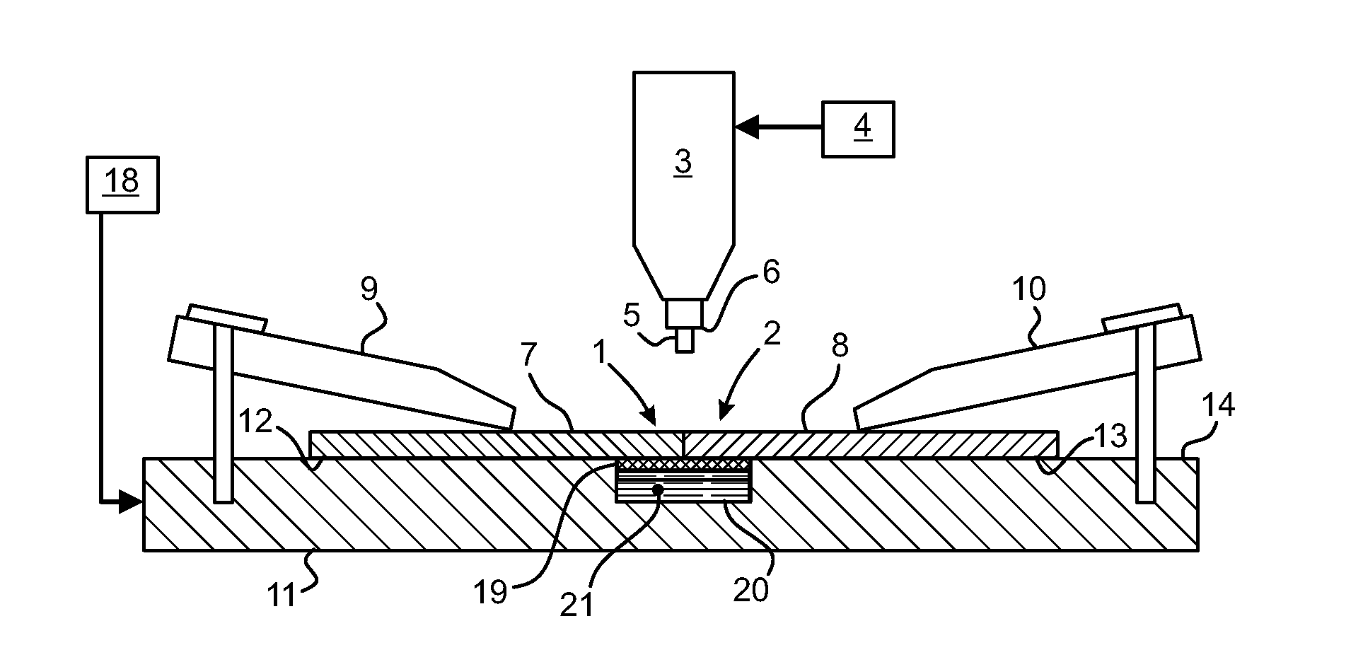
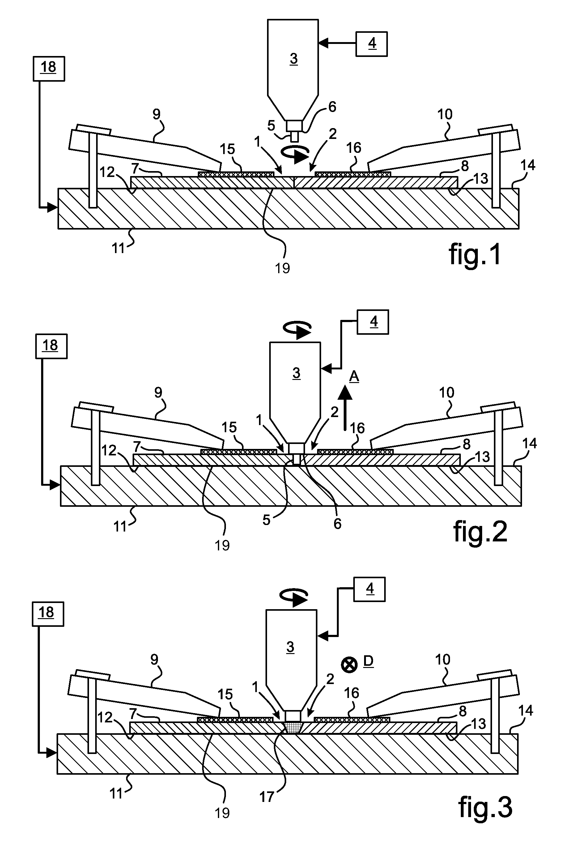
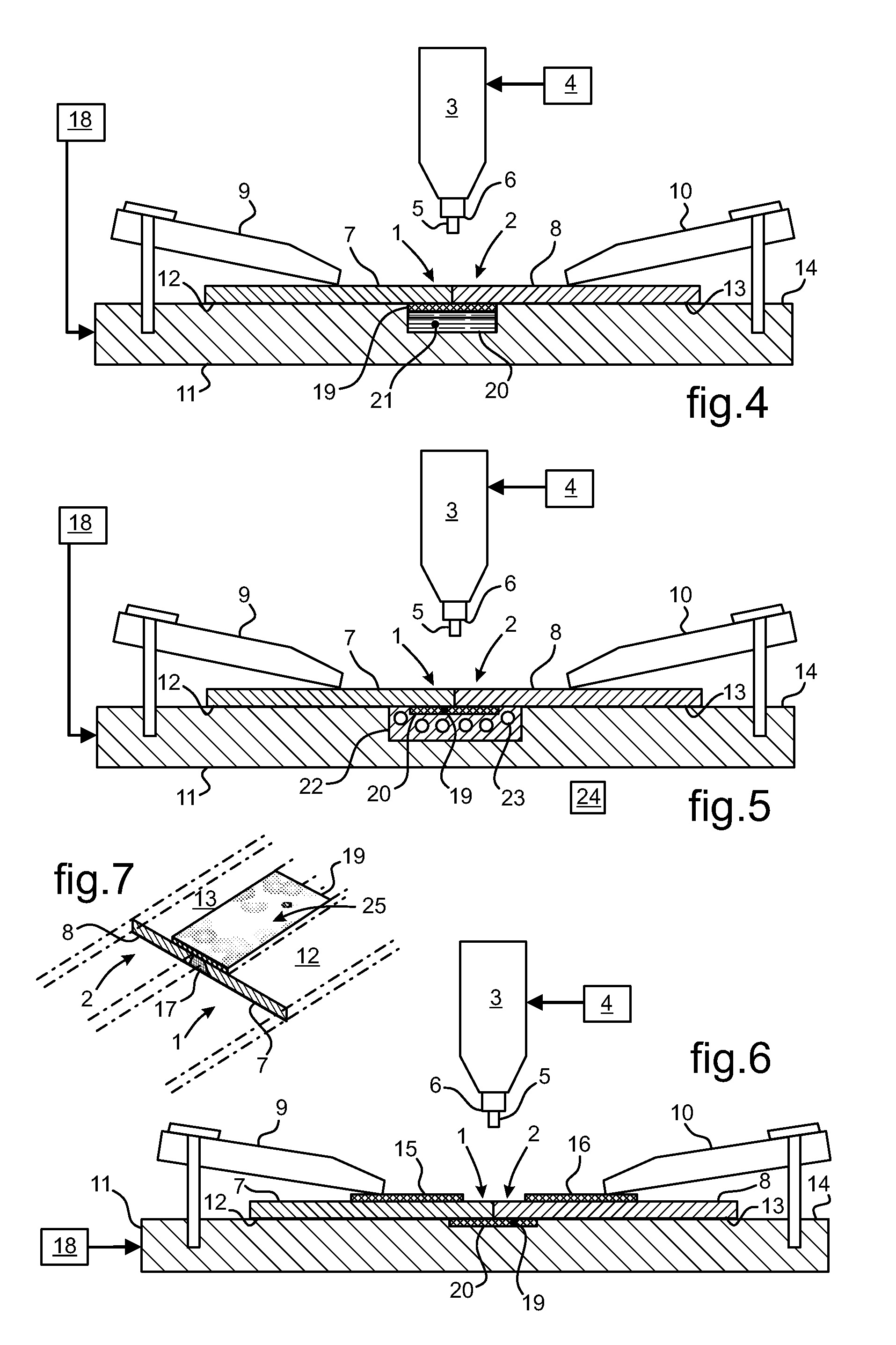
[0059]In FIGS. 1 to 3, a machine is organized to assemble together two plane parts 1 and 2 that are of small thickness, being about one millimeter thick. Assembly is performed more particularly using the known friction-welding technique. The machine comprises a chuck 3 that is driven in rotation by first motor means 4 and that carries a welding pin 5. The chuck 3 has a shoulder 6 that acts as a depth gauge, the welding operation being controlled in force as a result of the friction induced by the shoulder 6 rubbing against the top faces 7 and 8 of the parts 1 and 2 for assembling together. The machine is fitted with a set of clamps 9, 10 for pressing the parts 1 and 2 against an anvil 11. More particularly, the clamps 9 and 10 bear against the top faces 7 and 8 of each of the parts 1 and 2, which parts bear in reaction via their bottom faces 12 and 13 against a support face 14 of the anvil 11. The parts 1 and 2 are held pressed against the anvil 11 while being placed adjacent to eac...


PUM

PropertyMeasurementUnit
widthaaaaaaaaaa
lengthaaaaaaaaaa
thicknessaaaaaaaaaa

Abstract

The invention provides a method of assembling together two thin plane parts (1, 2) by friction welding. A main sheet (19) made of a material having high thermal conductivity is held against the parts (1, 2) for assembly. The main sheet (19) picks up the heat induced by the friction of a welding pin (5) against the parts (1, 2) for the purpose of forming the weld bead (17), and it dissipates this heat by radiation. Temperature regulation of the welding operation is obtained by the main sheet (19), ensuring that no localized excess heating occurs in the welding zone. The main sheet (19) is based on copper and presents a thickness that is less than the thickness of the parts (1, 2).

Description

FIELD OF THE INVENTION[0001]The invention relates to the technical field of friction welding for connecting together two plane or shaped metal parts, the method including an operation of controlling temperature during the welding operation. The method provides such a friction-welding method, and more particularly a technique of controlling temperature during the welding operation.BACKGROUND OF THE INVENTION[0002]Welding techniques include techniques performed by friction, such as friction stir welding (FSW). Such a technique is advantageous for assembling together metal parts for assembly that are plane or shaped, such as plates, sheets, or other analogous parts. The parts for assembly are held adjacent to each other and pressed against an anvil, by clamping or by some other analogous technique. The term “anvil” is used to designate any member suitable for forming a working surface or analogous member, with the parts being clamped thereto so that they are pressed against the anvil e...

Claims


Application Information

Patent Timeline
Patent Type & Authority Patents(United States)
IPC IPC(8): B23K20/12
CPCB23K20/1235B23K20/126B23K37/0408B23K2201/18B23K2101/18
Inventor ALLEHAUX, DELPHINEGATTI, JEAN-LOUP
Owner EUROCOPTER
Why Eureka
Try Eureka