
System for positioning of surgical inserts and tools

a technology for surgical inserts and positioning systems, applied in the field of image reconstruction, can solve the problems of obstructing the surgeon's limited field of view and freedom of movement within the confines of the abdominal cavity, and the inability to easily perform the alignment procedure of the ct image with the real-time fluoroscope image process, and achieves the effect of increasing the accuracy of such procedures

Active Publication Date: 2013-03-12
MAZOR ROBOTICS
View PDF7 Cites 37 Cited by
  • Summary
  • Abstract
  • Description
  • Claims
  • Application Information

AI Technical Summary

Benefits of technology

The present invention provides a new tracking and positioning system and method to help surgeons accurately position artificial discs or tools in spinal surgery procedures. The system uses a database of virtual implants and preoperative CT scans to determine the best position for the disc or instrument on a virtual model of the spine. It then projects this position onto real-life images in real-life fluoroscopy during surgery, allowing the surgeon to accurately position the instrument or disc. This system increases the accuracy of spinal surgery procedures and can be used for any suitable surgical insertion and positioning procedure. The invention also allows for the disc insertion without removing the target plate and can provide a stable and accurate spatial reference.

Problems solved by technology

The alignment procedure of the CT image with the real time fluoroscope images process cannot readily be performed using vertebrally attached registration plates, since such plates, unless mounted using a long holder that would then be prone to errors, would obstruct the surgeon's limited field of view and freedom of motion within the confines of the abdominal cavity where the operation is being performed.

Method used


Image

  • System for positioning of surgical inserts and tools
  • System for positioning of surgical inserts and tools
  • System for positioning of surgical inserts and tools

Examples


Embodiment Construction

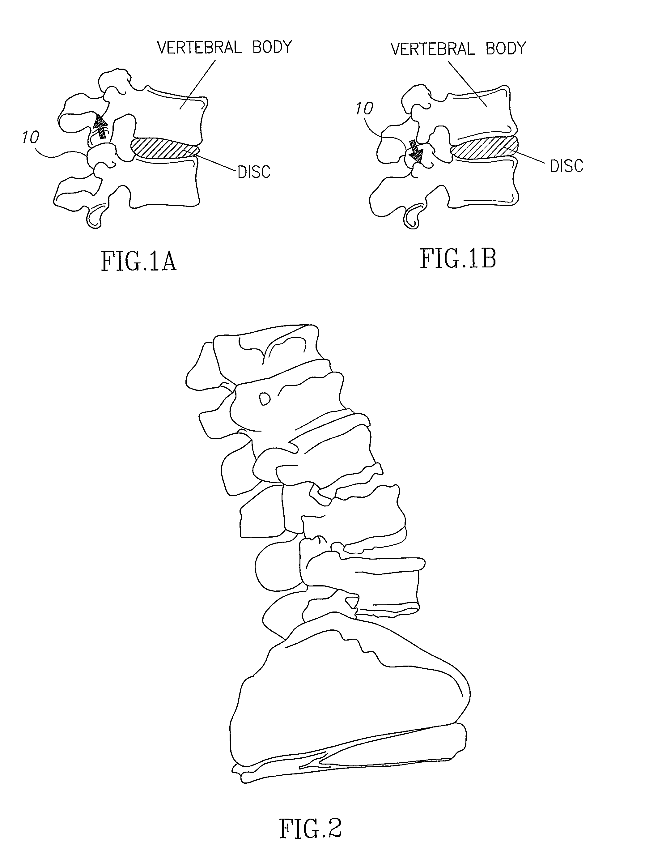
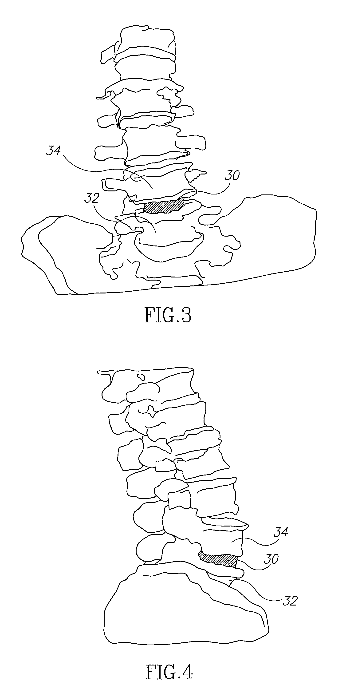
[0082]Reference is now made to FIG. 2, which illustrates schematically a model of the patient's spine, generated using data from preoperative CT scanning of the vertebrae. The model is built such that the separate vertebrae can be mutually virtually moved to enable insertion of the artificial disc between the desired vertebrae. The vertebrae are moved virtually by any of the generally available computer-based techniques, the most convenient being by use of the computer mouse, with the system software translating mouse movements to vertebral position movements. The vertebrae can be manipulated in all directions, both vertically, laterally and angularly, to enable correct insertion of the selected disc. The model takes into account the disc size and vertebral inclination. This is illustrated in FIGS. 3 and 4, which are respectively anterior and lateral views of the spinal model, showing how the artificial disc 30 is inserted virtually between the relevant adjacent vertebrae 32, 34.

[00...


PUM


Abstract

A tracking and positioning system and method to enable the precise positioning of an object or tool relative to its surgical surroundings, and in accordance with preoperative CT images of the operating site. When used for artificial spinal disc positioning, the system comprises a computing system incorporating in memory the preoperative CT data showing the two vertebrae and the predetermined disc position between them; a 3-D target having radio-opaque markers for attaching to one of the vertebrae to define the position of the vertebra in an intra-operative fluoroscope image of the spine; a tool for intra-operative insertion of the artificial disc, and a registration system for relating the intra-operative fluoroscope image to the preoperative CT data, such that the predetermined disc position is displayed in the fluoroscope image of the subject, thereby enabling the surgeon to place the artificial disc accurately in its intended position.

Description

CROSS-REFERENCE TO RELATED APPLICATIONS[0001]This application is a U.S. National Phase Application under 35 U.S.C. 371 of PCT International Application No. PCT / IL2007 / 001192, which has an international filing date of Sep. 25, 2007, and which claims priority from U.S. Provisional Patent Application Nos. 60 / 846,749, filed Sep. 25, 2006, and 60 / 875,561, filed Dec. 19, 2006, all of which disclosures are hereby incorporated by reference.FIELD OF THE INVENTION[0002]The present invention relates to the field of image reconstruction for ensuring the correct placement of surgical implants and tools, and especially to a system for ensuring correct surgical placement of artificial spinal discs.BACKGROUND OF THE INVENTION[0003]The use of artificial discs in spinal surgery to restore spinal mobility in patients with degenerative disc disease has been practiced for several years as an alternative to spinal fusion, and commercial systems for such disc replacement are available. The artificial disc...

Claims


Application Information

Patent Timeline
Patent Type & Authority Patents(United States)
IPC IPC(8): A61F2/44
CPCA61F2/4611A61B17/848A61B19/50A61F2/442A61F2002/3008A61F2002/4632A61F2250/0098A61B19/2203A61B19/201A61B2019/504A61B2019/505A61B2019/5466A61B2019/5238A61B2019/5268A61B2019/5287A61B2019/5289A61B34/10A61B34/30A61B90/11A61B2034/104A61B2034/105A61B2034/2068A61B2090/363A61B2090/364A61B2090/376A61B2090/3966
Inventor ZEHAVI, ELIKLEYMAN, LEONIDBATKILIN, EDDIE
Owner MAZOR ROBOTICS
Learn More