
Catalyst containment unit

a technology of catalyst containment and catalyst bed, which is applied in the direction of physical/chemical process catalysts, metal/metal-oxide/metal-hydroxide catalysts, and separation processes, etc. it can solve the problems that the radial flow catalyst bed structure has not been used in ammonia oxidation vessels before, and achieves reduced pressure drop, increased operational flexibility, and reduced compression costs

Inactive Publication Date: 2013-03-12
JOHNSON MATTHEY PLC
View PDF27 Cites 1 Cited by
  • Summary
  • Abstract
  • Description
  • Claims
  • Application Information

AI Technical Summary

Benefits of technology

The patent text describes a new design for a reactor that uses a catalyst containment unit to pass gases through the catalyst. This design offers improved flexibility and reduced compression costs compared to traditional reactors. It also introduces a new type of catalyst bed structure that has not been previously used in ammonia oxidation vessels. Overall, this patent presents a more efficient and flexible way to use catalyst in reactors.

Problems solved by technology

Radial flow reactors are known, however, to our knowledge none comprise a catalyst containment unit wherein an end member serves as suspending means by which the unit is secured within a reactor.
Moreover, to our knowledge, radial flow catalyst bed structures have not heretofore been used in ammonia oxidation vessels.

Method used


Image

  • Catalyst containment unit
  • Catalyst containment unit
  • Catalyst containment unit

Examples


Embodiment Construction

[0029]In a conventional nitric acid plant, the number of gauzes employed depends on the pressure at which the process is operated. For example in a plant operating at low pressure, e.g. up to about 5 bar abs., typically 20, often 35-45, may be employed. The gauzes, which are normally circular, may be incorporated individually into the reactor or may be pre-formed into a pad comprising a number of gauzes that may be welded at their periphery. The pad may comprise a combination of woven and knitted or possibly non-woven gauzes whose elemental composition may be the same or different. If adjacent woven gauzes are present, to facilitate replacement, they are preferably arranged so that their warps or wefts are at an angle of 45° to each other. Angular displacement, suitably at 90°, may also be used between adjacent woven gauzes to reduce opportunities for gas channeling.

[0030]Catchment gauzes based on palladium are desirably used in ammonia oxidation plants to act as so-called “getters”...


PUM

PropertyMeasurementUnit
pressuresaaaaaaaaaa
temperaturesaaaaaaaaaa
pressuresaaaaaaaaaa

Abstract

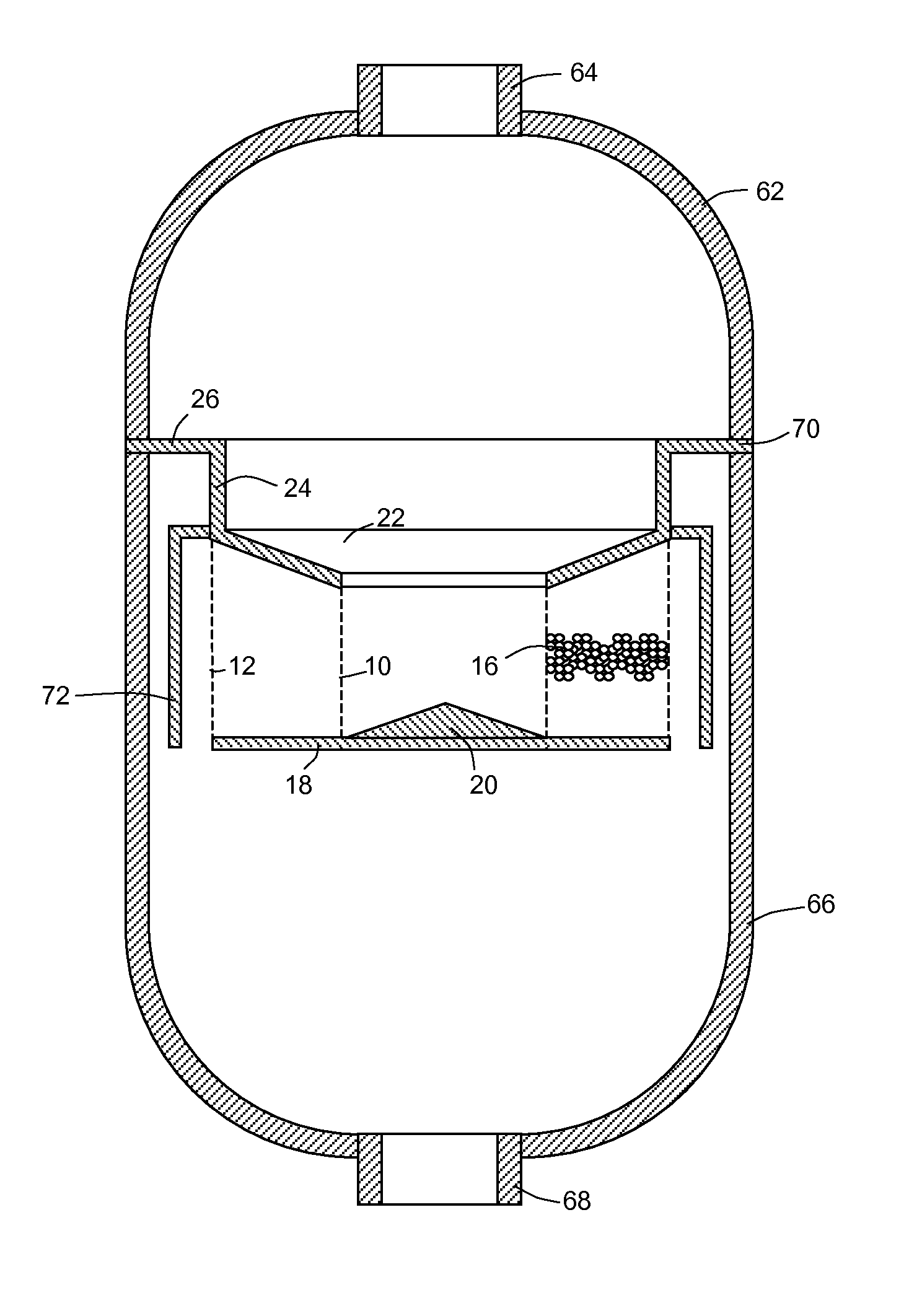
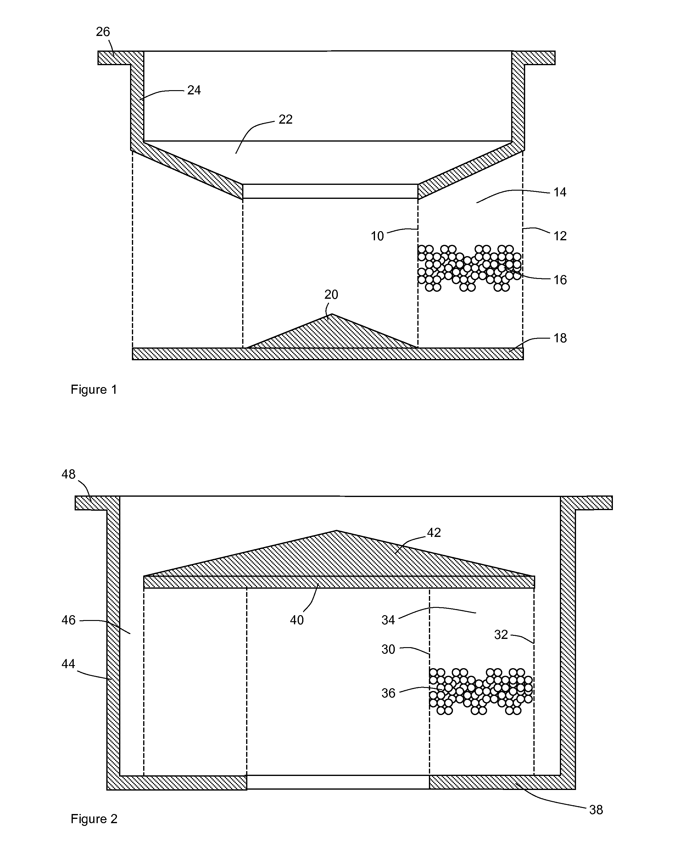
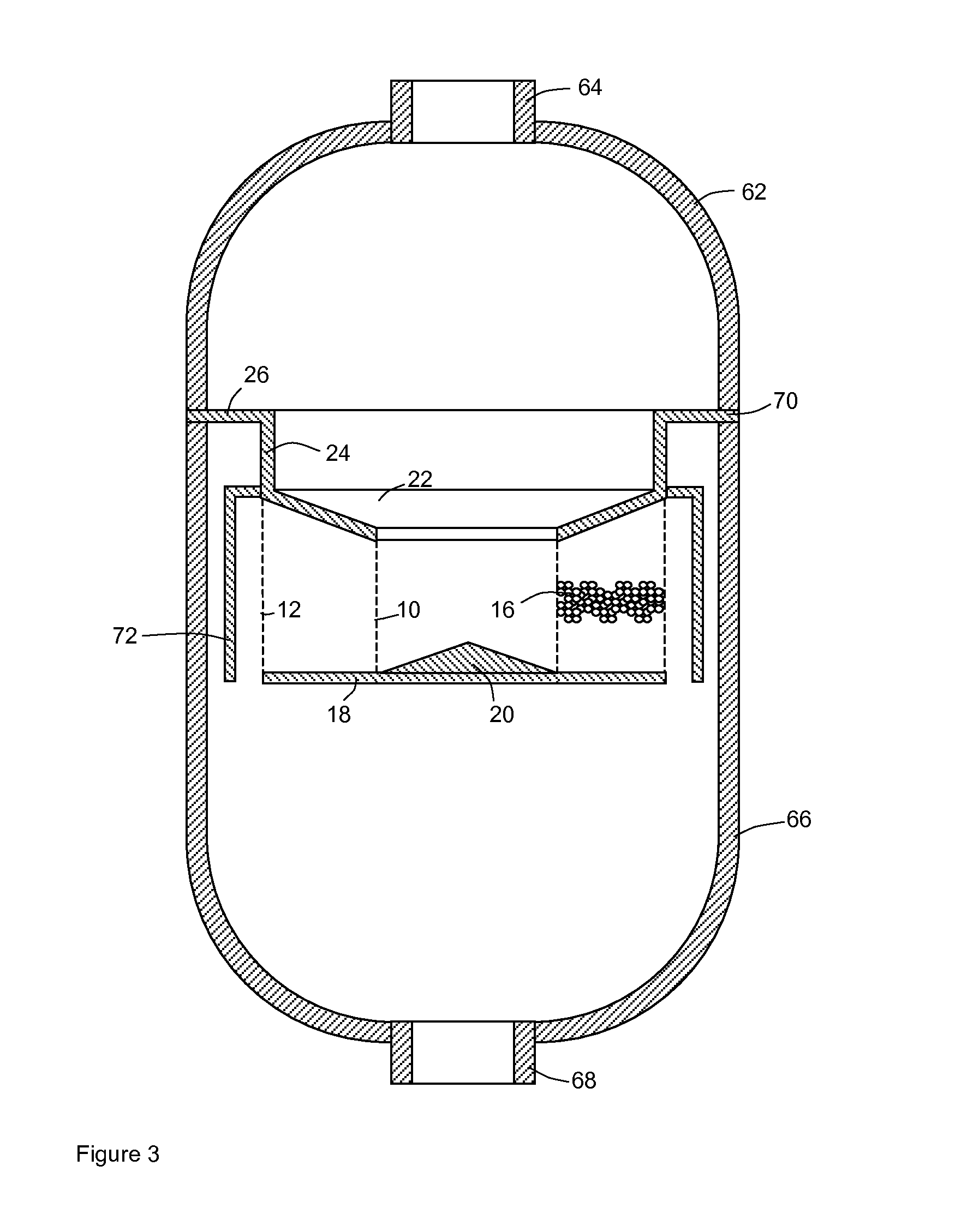
A catalyst containment unit, includes two concentric perforate members defining an annular space in which a particulate catalyst may be placed, and process fluid-impermeable end members mounted on the ends of the perforate members, wherein one end member extends across the unit to provide a closed end and the other end member closes the annular space thereby providing an open end through which gases may enter or exit the unit, and suspending means attached to one or both end members for securing the unit within an ammonia oxidation vessel. The unit may be suspended, for example, below a precious metal ammonia oxidation gauze pack and may contain a particulate ammonia oxidation catalyst or nitrous oxide abatement catalyst. A catalyst combination includes a precious metal ammonia oxidation catalyst gauze on a supporting framework and a particulate catalyst disposed in a catalyst containment unit.

Description

CROSS-REFERENCE TO RELATED APPLICATIONS[0001]This application is the U.S. National Phase application of PCT International Application No. PCT / GB2009 / 051205, filed Sep. 17, 2009, and claims priority of British Patent Application No. 0819094.4, filed Oct. 20, 2008.FIELD OF THE INVENTION[0002]This invention relates to apparatus for containing catalysts, particularly catalysts used in ammonia oxidation vessels, and processes using such apparatus.BACKGROUND OF THE INVENTION[0003]Ammonia oxidation is carried out industrially with air to generate nitric oxide, which used to make nitric acid (the Ostwald Process) or with air and methane to generate hydrogen cyanide (the Andrussow Process). In both processes, the reactant gases are mixed and passed at elevated temperature and pressure through a reaction vessel in which is placed a pack of platinum / rhodium gauzes that catalyse the oxidation reactions. The gauzes are typically circular and are supported on a frame or basket that holds them per...

Claims


Application Information

Patent Timeline
Patent Type & Authority Patents(United States)
IPC IPC(8): B01J8/00C01B21/26B23P23/00B23P17/04B01J35/02B01J8/02B01J35/00
CPCB01D53/8631B01J8/0214B01J19/2495B01J23/40B01J35/0006B01J35/04C01B21/265C01B21/28C01C3/0216C01C3/022B01D53/8634Y10T29/49716B01D2251/11B01D2251/208B01D2255/1021B01D2255/1023B01D2255/1025B01D2255/1026B01D2255/1028B01D2255/104B01D2255/106B01D2255/2025B01D2255/2045B01D2255/2047B01D2255/206B01D2255/2073B01D2255/20738B01D2255/20746B01D2255/20753B01D2255/20761B01D2255/2092B01D2255/30B01D2255/402B01D2255/405B01D2255/904B01D2255/9202B01D2257/402B01D2257/406B01J23/464B01J23/74B01J2208/00849B01J2208/00884B01J2208/025Y02C20/10B01J2219/00024Y02P20/151B01J35/19B01J35/56B01J8/02B01J19/18B01J19/24C01B21/26
Inventor ROE, STEPHEN PHILIP
Owner JOHNSON MATTHEY PLC
Learn More