
Profitable method for carbon capture and storage

a carbon dioxide and carbon dioxide technology, applied in the direction of hydrocarbons, hydrocarbon cracking, climate sustainability, etc., can solve the problems of threatening arctic ecosystems, endangering coastal communities, and limited use of ccs applications

Active Publication Date: 2013-03-12
REG SYNTHETIC FUELS LLC
View PDF3 Cites 24 Cited by
  • Summary
  • Abstract
  • Description
  • Claims
  • Application Information

AI Technical Summary

Benefits of technology

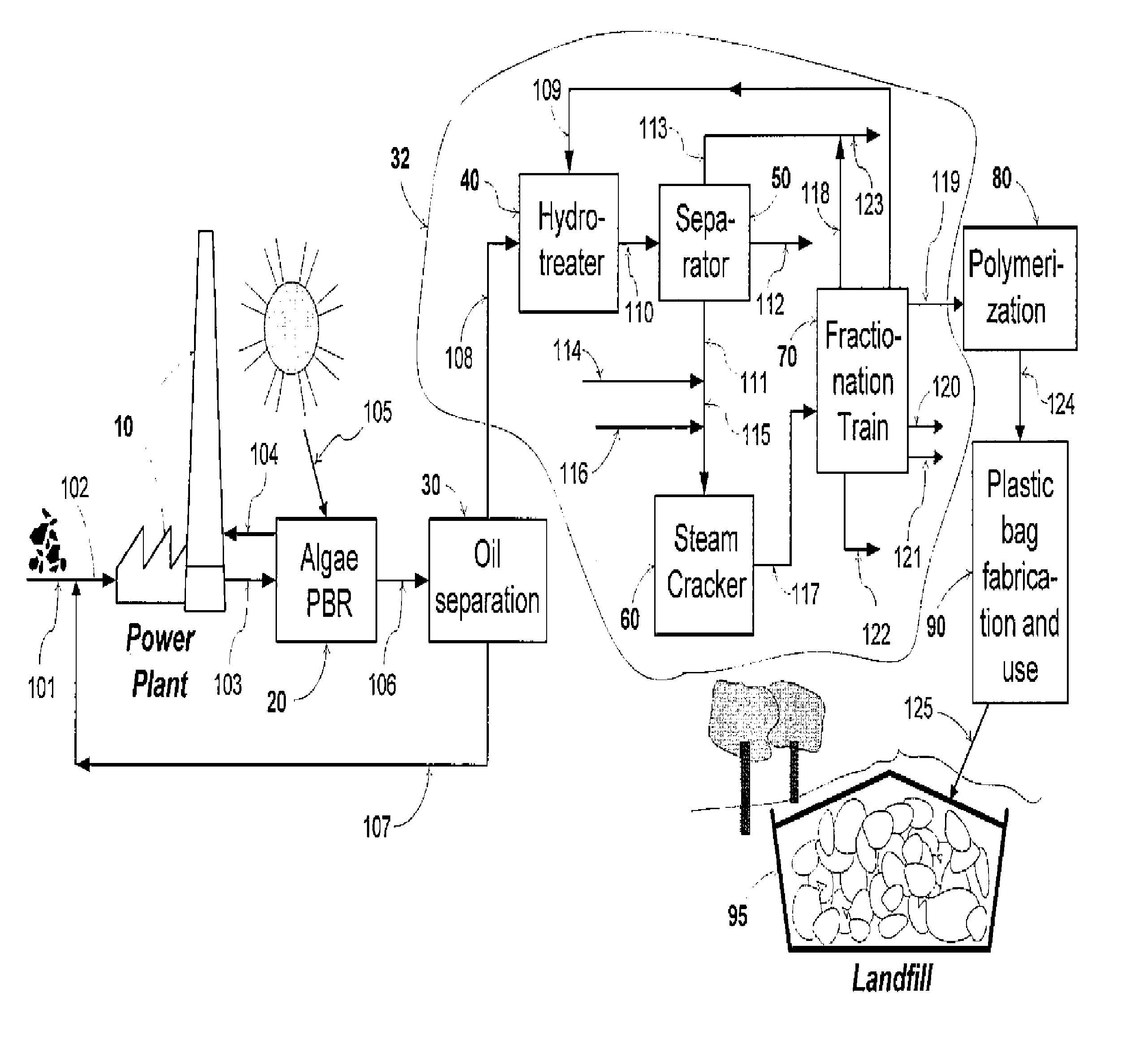
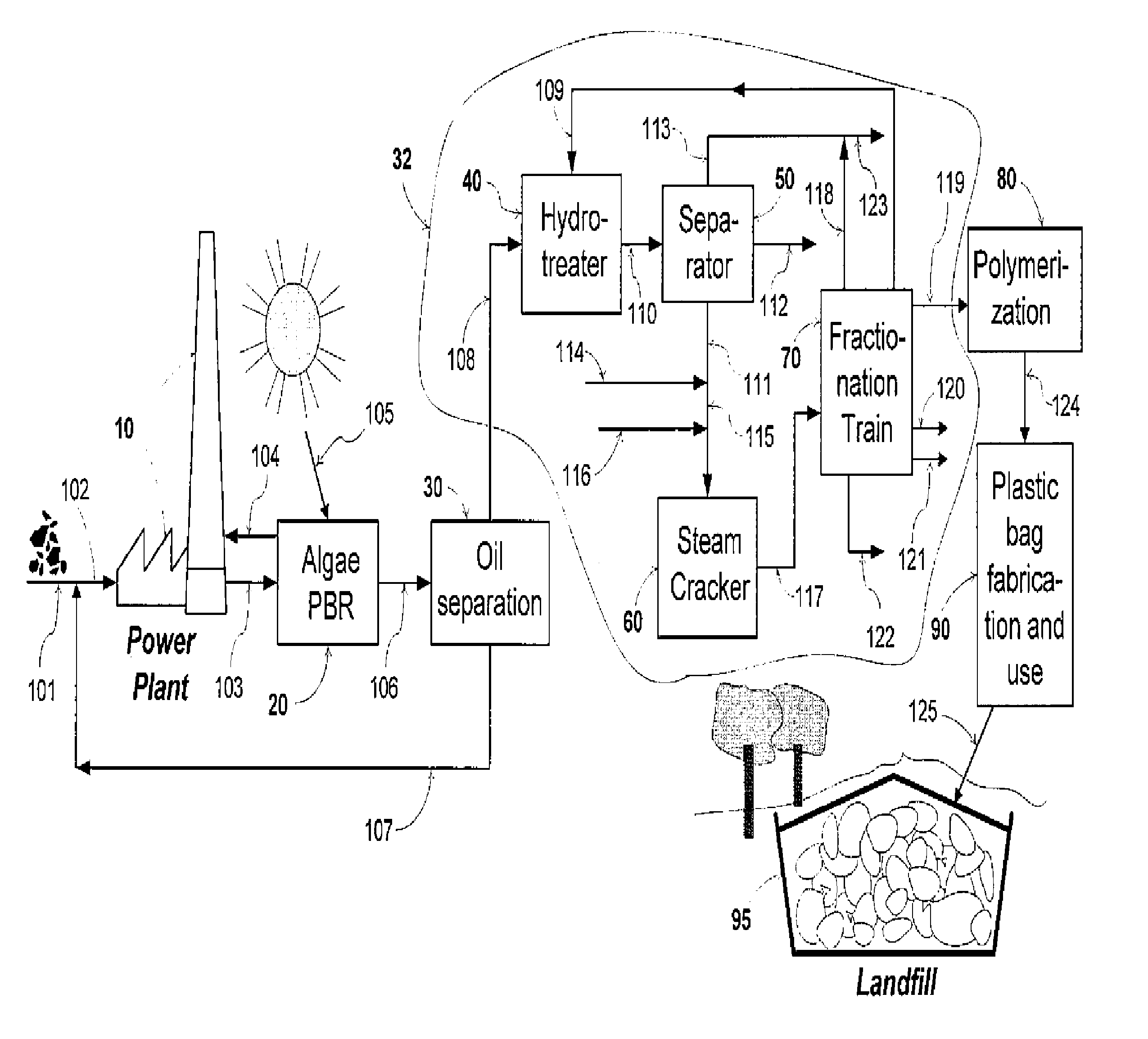
The patent describes a method for capturing and storing CO2 from a variety of sources, including power plants and landfills. The method involves photosynthetically converting CO2 into biomass, which can then be converted into paraffinic hydrocarbons. These hydrocarbons can then be cracked into light olefins, which can be polymerized into polyolefin plastics. By using this method, each ton of carbon in the plastic would represent 3.67 tons of CO2 removed from the atmosphere, stored within useful products, and ultimately sequestered in commercial landfills. The method is also market-friendly and can produce bio-based gasoline, hydrogen, and basic chemicals.

Problems solved by technology

Consequences of global warming include melting of polar ice caps and rising sea levels, threatening arctic ecosystems and endangering coastal communities.
Although these gas absorption methods are technically mature, their use in CCS applications has been limited.
This is in part due to the fact that not all geological formations are well-suited for CO2 storage.
Perhaps more importantly, the hesitation to adopt such CCS processes stems from the fact that the investment and operating cost for capture, compression and storage of CO2 brings the carbon emitting plant owner no corresponding financial return.
However, the efficiency and effectiveness of this approach has been questioned.
Unless stored under a controlled environment underground, the biomass is likely to decompose and re-release the CO2.
Furthermore, as in the case of other prior art CCS processes, there is little economic incentive for adoption of this method.
However, like terrestrial plants, algae are biodegradable.
However these processes require construction of new and expensive plants.
Furthermore, these olefin production routes are not believed to be competitive with steam cracking of hydrocarbons, which is the technology used in all world scale olefin plants today.
Although the biofuel prior art provides various methods and systems for producing such compositions, the prior art methods and systems do not address early adoption issues such as capital costs for building new plants.

Method used


Image

  • Profitable method for carbon capture and storage
  • Profitable method for carbon capture and storage

Examples


example 1

Steam Cracking of Biomass-Based Hydrocarbons

[0073]A biomass-based oil composition made of a blend of animal fats and spent vegetable oils was prepared. All biofeed components were obtained from Tyson Foods (Springdale, Ark.). The makeup of this blend is provided in Table 1.

[0074]

TABLE 1Make-up of Bio Oil BlendComponentAmount (wt %)Poultry Fat46Yellow Grease18Brown Grease18Floatation Grease9Grease from Prepared9Foods

[0075]The feed blend of Table 1 was subjected to acid wash pretreatment whereby phosphorus and metal contaminants were partially removed. The properties of the pretreated bio oil, including residual contaminants and fatty acid profile, are given in Table 2.

[0076]

TABLE 2Summary of analytical data on pretreated bio oil feed blendContaminants / Quality AnalysisAsh (ppm wt)67.2Nitrogen (ppm wt)1006Sulfur (ppm wt)111Acid Value (mg KOH / g)129Karl Fisher Moisture (wt %)0.85Moisture and all Volatiles (wt %)1.30Insoluble impurities (wt %)0.04Unsaponifiables (wt %)1.03Peroxide value (...


PUM

PropertyMeasurementUnit
operating pressuresaaaaaaaaaa
temperatureaaaaaaaaaa
temperaturesaaaaaaaaaa

Abstract

The present invention generally relates to a method for sequestering carbon dioxide. Biomass is converted into paraffinic hydrocarbons. The paraffinic hydrocarbons are steam cracked into olefins. The olefins are polymerized into non-biodegradable polyolefins.

Description

CROSS REFERENCE TO RELATED APPLICATIONS[0001]Not applicable.FEDERALLY SPONSORED RESEARCH[0002]Not applicable.FIELD OF THE INVENTION[0003]The present invention relates to a method for sequestering carbon dioxide. The present invention also relates to a process for producing bio-based olefins, polyolefins, and motor gasoline.BACKGROUND OF THE INVENTION[0004]There is a growing consensus among climate scientists that the increasing concentration of heat trapping carbon dioxide (CO2) in the atmosphere—mainly from combustion of fossil fuels—is contributing to global warming. Consequences of global warming include melting of polar ice caps and rising sea levels, threatening arctic ecosystems and endangering coastal communities.[0005]Climate scientists argue that during most of human history—up to the industrial revolution—the air held no more than 275 ppm CO2. The atmospheric CO2 concentration in 2009 was 385 ppm and rising. To slow down global warming, CO2 from high fossil fuel emission s...

Claims


Application Information

Patent Timeline
Patent Type & Authority Patents(United States)
IPC IPC(8): C08F2/00C10G57/02C08F10/02C01B32/55
CPCC08F36/06C10K3/006C10G1/002C08F10/00C08F2/00C10G50/00C10G69/06C10G69/14C10L1/06C10G2/32C10G3/50C10G9/00C10G57/02C07C29/04C10J2300/0909C10J2300/1659C10J2300/1681C08F110/02C08F110/06C10G2300/4043C10G2300/1014C10G2300/1018C10G2300/1022C10G2400/20C10G2400/22C10G2300/807C01B2203/86C10G2400/02Y02E50/32Y02P30/40C10G9/36Y02E50/30Y02P30/00
Inventor ABHARI, RAMIN
Owner REG SYNTHETIC FUELS LLC
Learn More