Method for manufacturing light set with surface mounted light emitting components

a technology of surface mounted light emitting components and manufacturing methods, which is applied in the manufacture of electric discharge tubes/lamps, lighting and heating devices, lighting support devices, etc., can solve the problems of difficult control of welding quality, difficult repetitive manufacturing process, poor reliability, etc., and achieves accurate positioning, reduce manufacturing time, and increase efficiency

Active Publication Date: 2013-03-19
REAL BONUS
View PDF4 Cites 33 Cited by
  • Summary
  • Abstract
  • Description
  • Claims
  • Application Information

AI Technical Summary

Benefits of technology

[0007]Therefore, the primary objective of the present invention is to provide a method for manufacturing a light set with surface mounted light emitting components, wherein the method makes fabrication quite easy to quickly and accurately manufacture a light set with surface mounted light emitting components, thereby overcoming the problems in production manufacturing of the conventional art.
[0010]The technique used by the present invention of grinding the conducting wires all together after being wound on a winding control architecture not only reduces manufacturing time and increases efficiency, but can also control the positions of the exposed conductors. By adjusting the winding pitch, it allows each surface mounted light emitting component to be equally spaced on the conducting wires of the end product to achieve accurate positioning.
[0011]Furthermore, there is no need for the leads of the surface mounted light emitting components to be soldered one by one. Instead, the leads are directly straddled on and between corresponding contact-pad areas, and are electrically connected to the conductors of the conducting wires by the conductive paste. Thus, the fabrication process is easy, convenient, and effectively increases the efficiency of production.
[0012]Moreover, the contact-pad areas provide positioning for the surface mounted light emitting components, allowing the contact area between the surface mounted light emitting components and the conducting wires to be larger. The surface is further covered by a package providing stability in the overall structure, making it less prone to damage and separation due to external impact, thereby improving reliability.

Problems solved by technology

However, weld quality is difficult to control.
The connection between a semiconductor light emitting component and a conducting wire is affected by the weld quality, and thus semiconductor light emitting components are prone to damage, separation, and other problems due to external impact, resulting in poor reliability.
In addition, when a plurality of semiconductor light emitting components are combined or serially connected, every pair of leads on a plurality of semiconductor light emitting components is soldered one by one onto conducting wires, resulting in a difficult repetitive manufacturing process.
When a large number of semiconductor light emitting components are combined, the overall production rate is low.
Also, accurate positioning of the semiconductor light emitting components on conducting wires is difficult, resulting in non-uniform spacing and poor quality of the product.

Method used


Image

  • Method for manufacturing light set with surface mounted light emitting components
  • Method for manufacturing light set with surface mounted light emitting components
  • Method for manufacturing light set with surface mounted light emitting components

Examples


Embodiment Construction

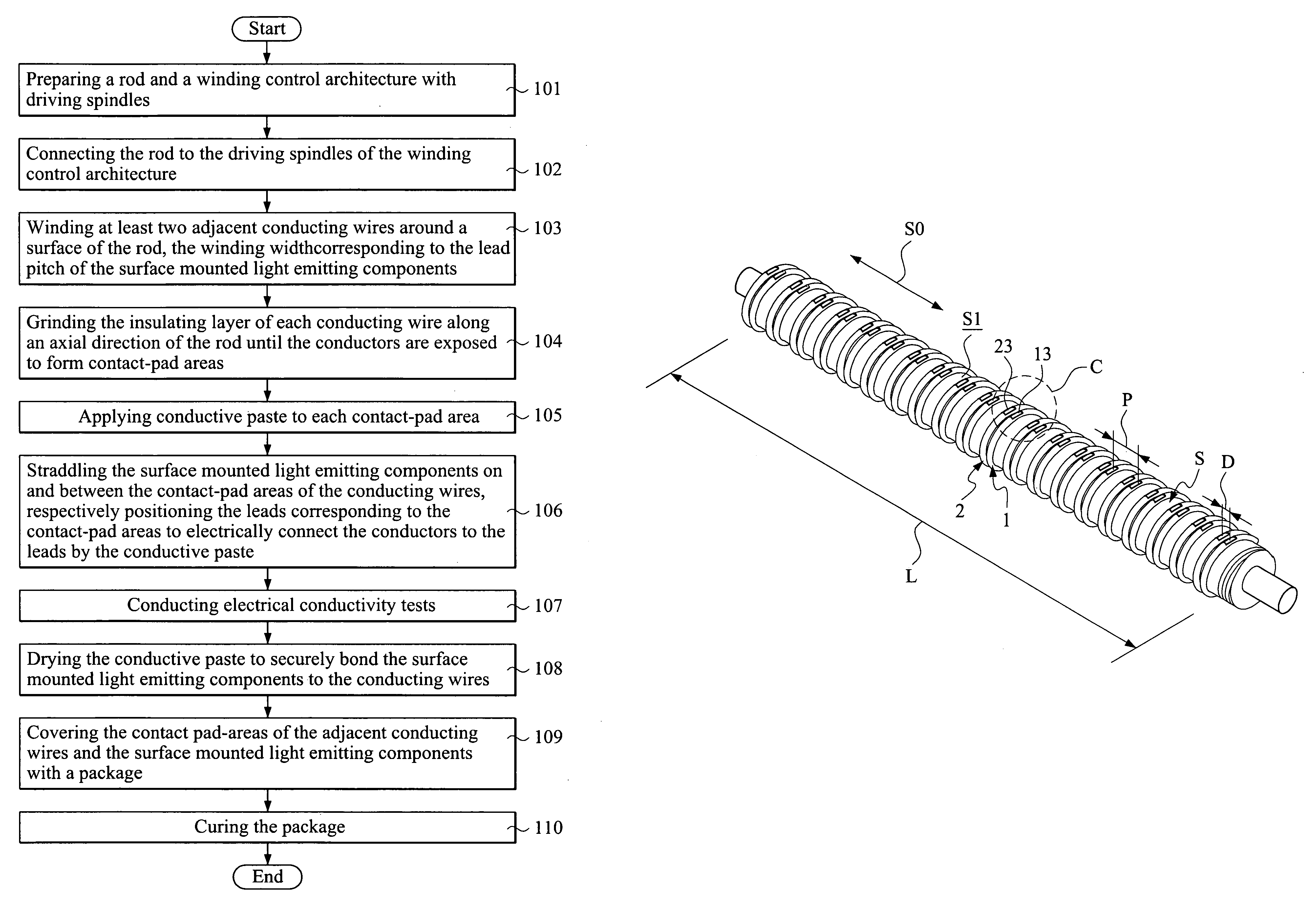
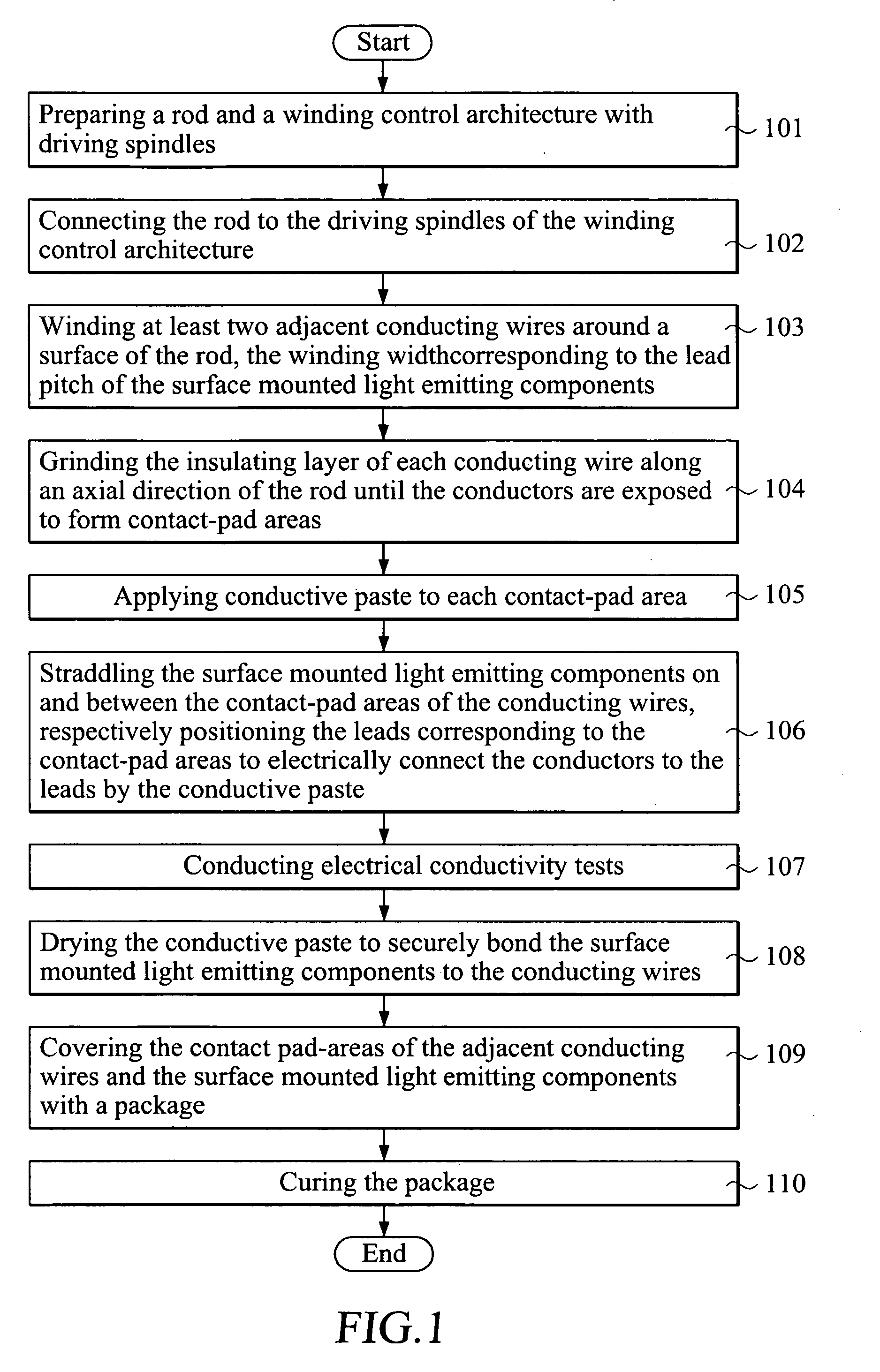
[0026]Please refer to FIG. 1 showing a flow chart of the steps of a preferred embodiment of the present invention. Reference is also made to FIG. 2 through FIG. 12 and detailed descriptions of the preferred embodiment of the present invention hereinafter.

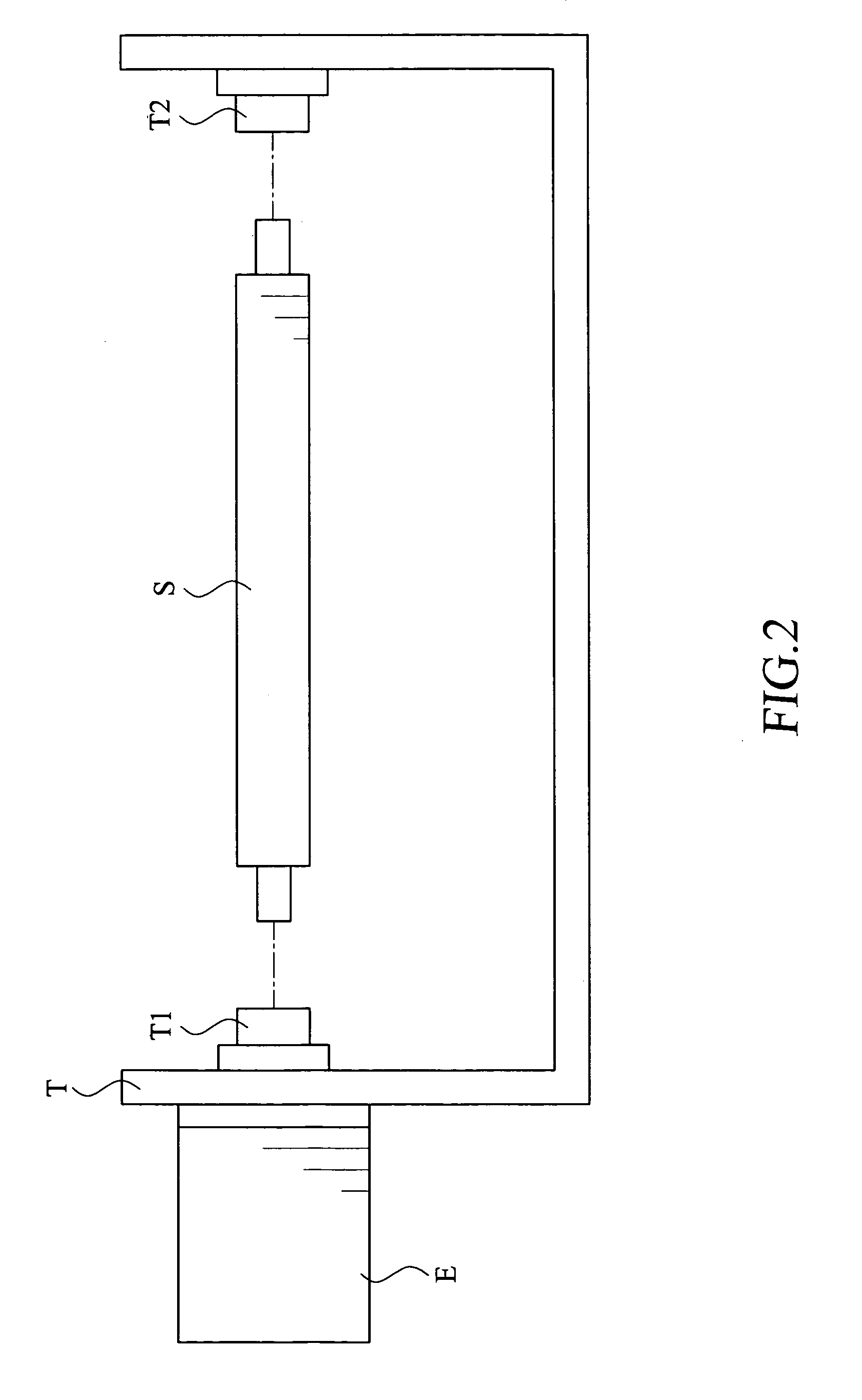
[0027]Please refer to FIGS. 2, 3, and 4. A rod S having a predetermined length L and a winding control architecture T with corresponding driving spindles T1, T2 are prepared first (Step 101). Then, the rod S is connected to the driving spindles T1, T2 of the winding control architecture T, and the driving spindles T1, T2 are driven to rotate by a winding machine E (Step 102).

[0028]Please refer to FIG. 5. When the rod S is rotated by the driving spindles T1, T2 of the winding control architecture T along a rotation direction R, at least two conducting wires 1, 2 with insulating layers 11, 21 coated thereon and with a predetermined width -D between the two conducting wires 1, 2 are wound around a surface S1 of the rod S, wherein the w...


PUM

PropertyMeasurementUnit
lengthaaaaaaaaaa
widthaaaaaaaaaa
areasaaaaaaaaaa

Abstract

A method for manufacturing a light set with surface mounted light emitting components is disclosed. A rod having a predetermined length and a winding control architecture with corresponding driving spindles are prepared first. The rod is driven to rotate by a winding machine via driving spindles to wind conducting wires. The insulating layer of each conducting wire is then ground along an axial direction of the rod to expose the conductor of each conducting wire to form contact-pad area. A conductive paste is applied to each contact-pad area, and the surface mounted light emitting components are straddled thereon. Each lead of the surface mounted light emitting components is respectively positioned corresponding to the contact-pad areas, and is electrically connected to the conductors by the conductive paste. The contact-pad areas and the surface mounted light emitting component are then covered with a package.

Description

FIELD OF THE INVENTION[0001]The present invention relates to the process design of a light set with semiconductor light emitting components, and more particularly, to a method for manufacturing a light set with surface mounted light emitting components.BACKGROUND OF THE INVENTION[0002]In recent years, semiconductor light emitting components have gradually replaced traditional lighting devices. The light emitting diode (LED) has a lot of advantages, such as small volume, quick response time, long service life, not easily attenuated, rigid outer casing, vibration-resistant, ability to emit different colors of light (including invisible light), allowing oriented-design, low voltage, low current, low conversion loss, low thermal radiation, easily mass-producible, environmental friendly, etc.[0003]A conventional LED includes an LED dice encapsulated in a lamp-shaped package. A pair of leads is extended from the LED dice through the package for electrically connecting to external power so...

Claims


Application Information

Patent Timeline
Patent Type & Authority Patents(United States)
IPC IPC(8): H01R43/00H05K13/00
CPCF21K9/00F21S4/001F21Y2101/02Y10T29/49169Y10T29/5122Y10T29/53213Y10T29/49171F21S4/10F21Y2115/10
Inventor TSAI, KENNETH
Owner REAL BONUS
Why Eureka
Try Eureka