Method of and apparatus for grinding cams of a camshaft

a camshaft and camshaft technology, applied in the direction of grinding machines, grinding machine components, manufacturing tools, etc., can solve the problems of difficulty in accessing the machine by operating personnel, inconvenient grinding at high removal rate, and inability to support the camshaft with steady rests, so as to improve the access to the machine and increase the removal rate

Active Publication Date: 2013-03-19
EMAG HLDG GMBH
View PDF9 Cites 4 Cited by
  • Summary
  • Abstract
  • Description
  • Claims
  • Application Information

AI Technical Summary

Benefits of technology

[0004]The object of the invention is to improve the above-described method and machine in such a way that grinding with increased removal rates is possible. Simultaneously, access to the machine is to be improved.

Problems solved by technology

As a result, the operating personnel can only access the machine with difficulty.
In addition, the camshaft cannot be supported with steady rests, as the space needed for them is occupied by the finishers.
Hence the machine is not suitable for grinding at high removal rates.

Method used


Image

  • Method of and apparatus for grinding cams of a camshaft
  • Method of and apparatus for grinding cams of a camshaft
  • Method of and apparatus for grinding cams of a camshaft

Examples


Embodiment Construction

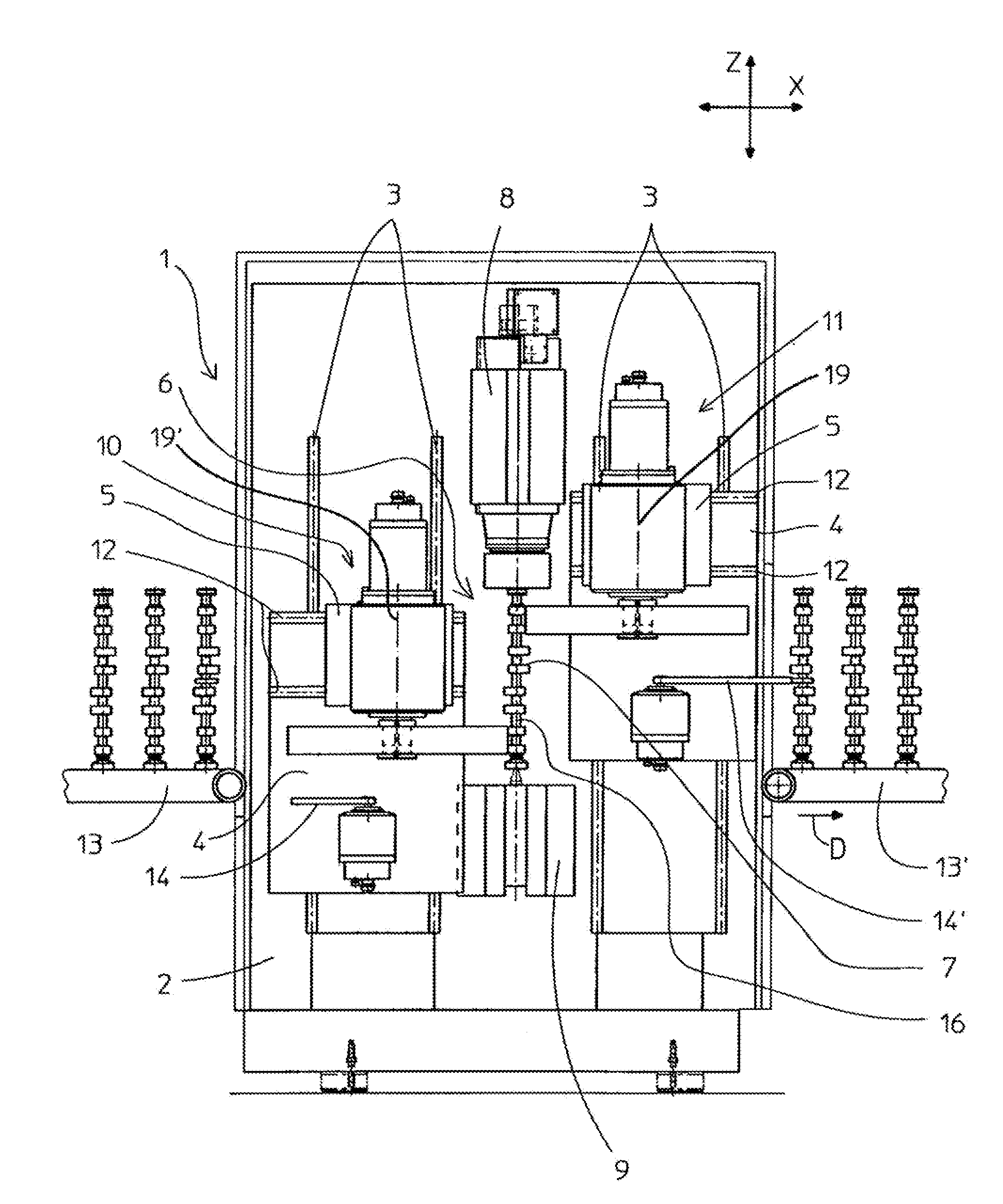
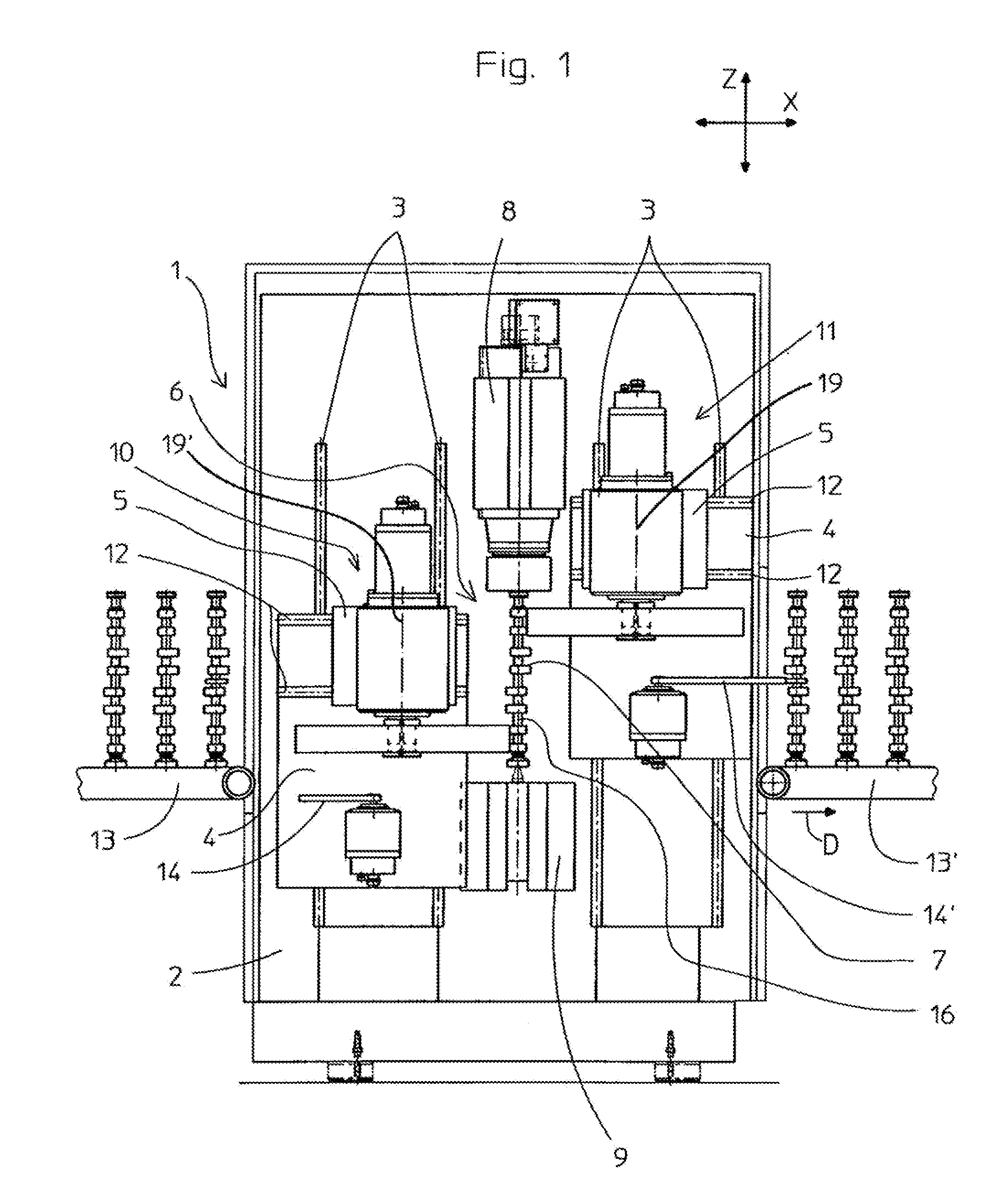
[0012]FIG. 1 shows an apparatus 1 for machining camshafts 7, details of the drive, its controller, and the housing not essential to the invention not being shown. The camshafts 7 are chucked in a workpiece holder 6 consisting of a headstock 8 and a tailstock 9 and rotated. Two grinders 10 and 11 diametrally flank the workpiece rotation axis 16. They can each move in two mutually perpendicular directions relative to each other (X and Z axis) on a machine frame 2. To this end, vertical guides 3 are provided on the frame 2 for vertically movable slides 4, and these in turn have respective horizontal guides 12 for horizontally movable carriages 5. The transporting in an out of the camshafts 7 is done by respective conveyors 13 and 13′. Loading and unloading is performed by respective workpiece grabs 14 and 14′.

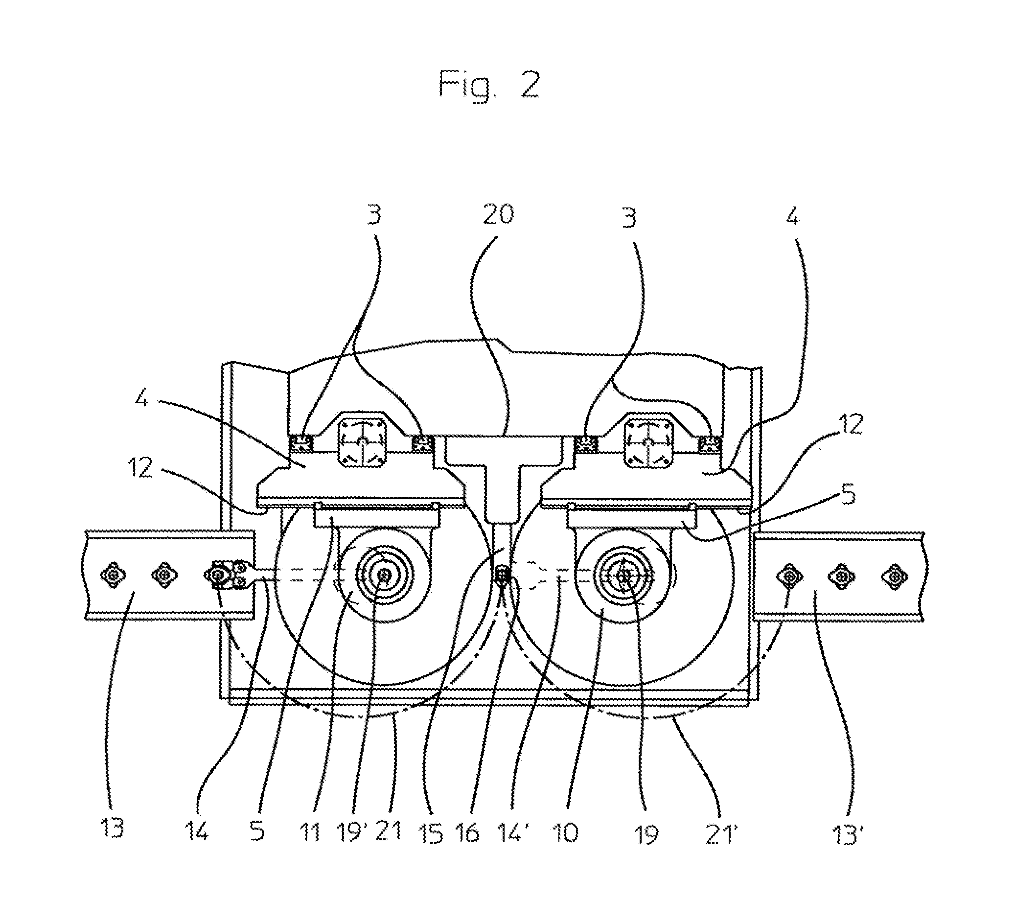
[0013]FIG. 2 shows that the workpiece rotation axis 16 and rotation axes 19 and 19′ of the grinders 10 and 11 are coplanar. A steady rest 15 is mounted between the vertical guides...


PUM

PropertyMeasurementUnit
feed speedaaaaaaaaaa
speedaaaaaaaaaa
rotationaaaaaaaaaa

Abstract

The invention relates to a method and a device for grinding cams of a camshaft (7) in a clamp with two grinding spindles (10, 11), wherein the cams or cam pairs are each arranged in a mirror image relative to the workpiece rotation axis (16), wherein the camshaft (7) is tensioned and rotated about the longitudinal axis thereof. In the device for carrying out the method, the camshaft (7) can be inserted into the workpiece receiver (6) from the side lying opposite the at least one back stay (15) by means of the loading device.

Description

CROSS REFERENCE TO RELATED APPLICATIONS[0001]This application is the US-national stage of PCT application PCT / DE2008 / 000542, filed 12 Apr. 2008, published 18 Dec. 2008 as WO2008 / 151586, and claiming the priority of German patent application 102007027832.4 itself filed 13 Jun. 2007.FIELD OF THE INVENTION[0002]The invention concerns a method of and an apparatus for grinding cams of a camshaft.BACKGROUND OF THE INVENTION[0003]From JP 2005052912, a machine for finish machining of camshafts is known. To simultaneously machine all the cams, a corresponding number of finishers are positioned around the camshaft. As a result, the operating personnel can only access the machine with difficulty. In addition, the camshaft cannot be supported with steady rests, as the space needed for them is occupied by the finishers. Hence the machine is not suitable for grinding at high removal rates. Moreover, for loading and unloading, multi-axial sequences of motion are required because the camshafts have...

Claims


Application Information

Patent Timeline
Patent Type & Authority Patents(United States)
IPC IPC(8): B24B19/12
CPCB24B19/12B24B27/0076
Inventor SCHMITZ, ROLAND
Owner EMAG HLDG GMBH
Why Eureka
Try Eureka