Method for manufacturing joined sheet material, joined sheet material and method for manufacturing optical display unit

a technology of joining sheet and joining sheet, which is applied in the direction of lamination, packaging, decorative surface effects, etc., can solve the problems of difficult to peel off only the separator with a probability of 100%, and the inability to only peel off the separator

Inactive Publication Date: 2013-03-19
NITTO DENKO CORP
View PDF13 Cites 5 Cited by
  • Summary
  • Abstract
  • Description
  • Claims
  • Application Information

AI Technical Summary

Benefits of technology

[0023]For example, the first and / or second joining member may be an adhesive tape or the like. For example, a joining method in the first joining step may include opposing the end faces of the first and second sheet products to each other and pressing a heat sealing tool directly against the surfaces of the opposed sheet portions to join the surfaces of the sheet portions by heat fusion. In this case, the sheet surface member produced through melting and solidification corresponds to the first joining member. In the joining step, a single joining member is preferably used, and it is more preferably an adhesive tape. It is because when such an adhesive tape is used, the joining process can be completed in a short time even by hand. The first and / or second joining member is preferably placed over the whole transverse length of the sheet products. The second joining member is provided on at least an exposed portion resulting from the removal of the intended member. Therefore, the second joining member preferably has a width larger than the width of the intended member so that the surface protecting member sides of the first and second sheet products can be joined with it.
[0028]When the joined sheet product is obtained by the manufacturing method described above, for example, the sheet products can be continuously processed without stopping the manufacturing line. Therefore, it has high productivity. The joined sheet product may be wound into a roll, which may be stored or transported as a raw material roll. The structure of the joined sheet product makes it possible to smoothly and properly peel off only the release film placed on the pressure-sensitive adhesive without interference with other constituent members. In the process of peeling off the release film, the first and second sheet products are properly kept joined by the second joining member, which joins the surface members of the sheet products on the opposite side from the release film. Therefore, when the sheet product, from which the release film is peeled off, is attached to the desired object with the pressure-sensitive adhesive interposed therebetween, the continuous operation can be successfully retained, and the trouble with the continuous production can be significantly reduced.
[0046]As described above, the sheet products are joined without being overlapped with each other, so that only the release film can be accurately peeled off in a continuous process. In addition, the first and second joining member can each provide a sufficient adhering force, so that the joint portion can be prevented from breaking during the feeding. Therefore, the cutting step and the bonding step can be continuously performed, so that the optical display unit can be manufactured with significantly improved productivity.
[0048]In the defect inspection, any defect in the optical film can be inspected, regardless of whether the release film has any defect such as retardation existing in the release film and foreign matter or scratches adhering to or existing in the release film. The release film to be attached again to the sheet product may be a used or new one. In order that the release film to be attached again to the sheet product may be continuously supplied, the process preferably includes opposing the transverse end faces of release films to each other and joining, with a joining member, the opposite surfaces of the release films from the surfaces to be attached to the sheet product. This process makes it possible to continuously peel off only the release film attached again to the sheet product.

Problems solved by technology

However, when the end portions are layered and joined as mentioned above, it is impossible to peel off only the separator.
In this case, however, delamination sometimes starts from the pressure-sensitive adhesive on the surface protecting film side, and it is difficult to peel off only the separator with a probability of 100%.
Such a case is not preferred because of low continuous productivity, and it has been demanded to properly peel off only the release film.

Method used


Image

  • Method for manufacturing joined sheet material, joined sheet material and method for manufacturing optical display unit
  • Method for manufacturing joined sheet material, joined sheet material and method for manufacturing optical display unit
  • Method for manufacturing joined sheet material, joined sheet material and method for manufacturing optical display unit

Examples


embodiment 1

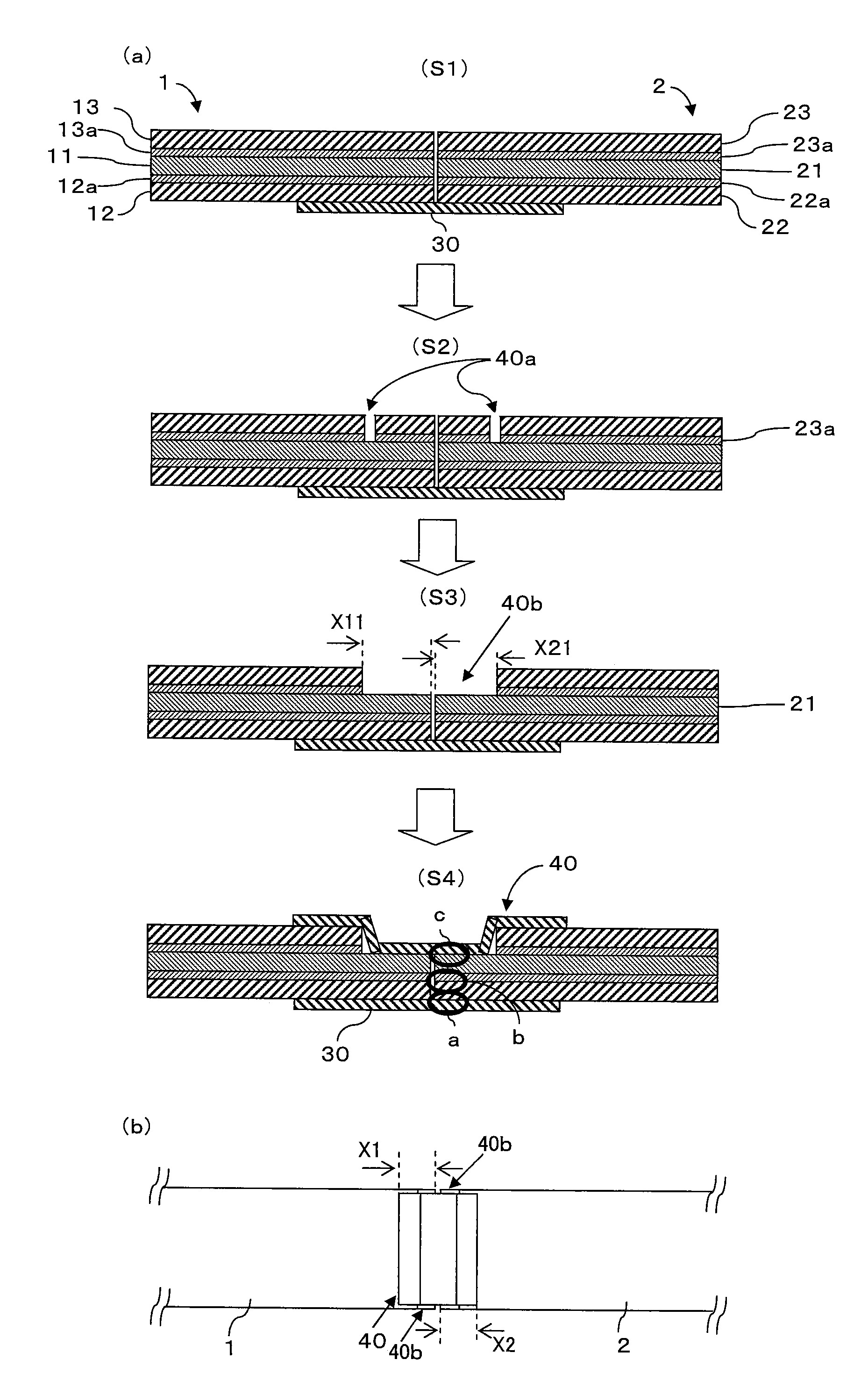
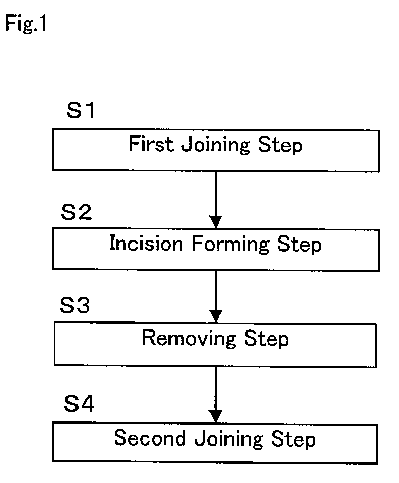
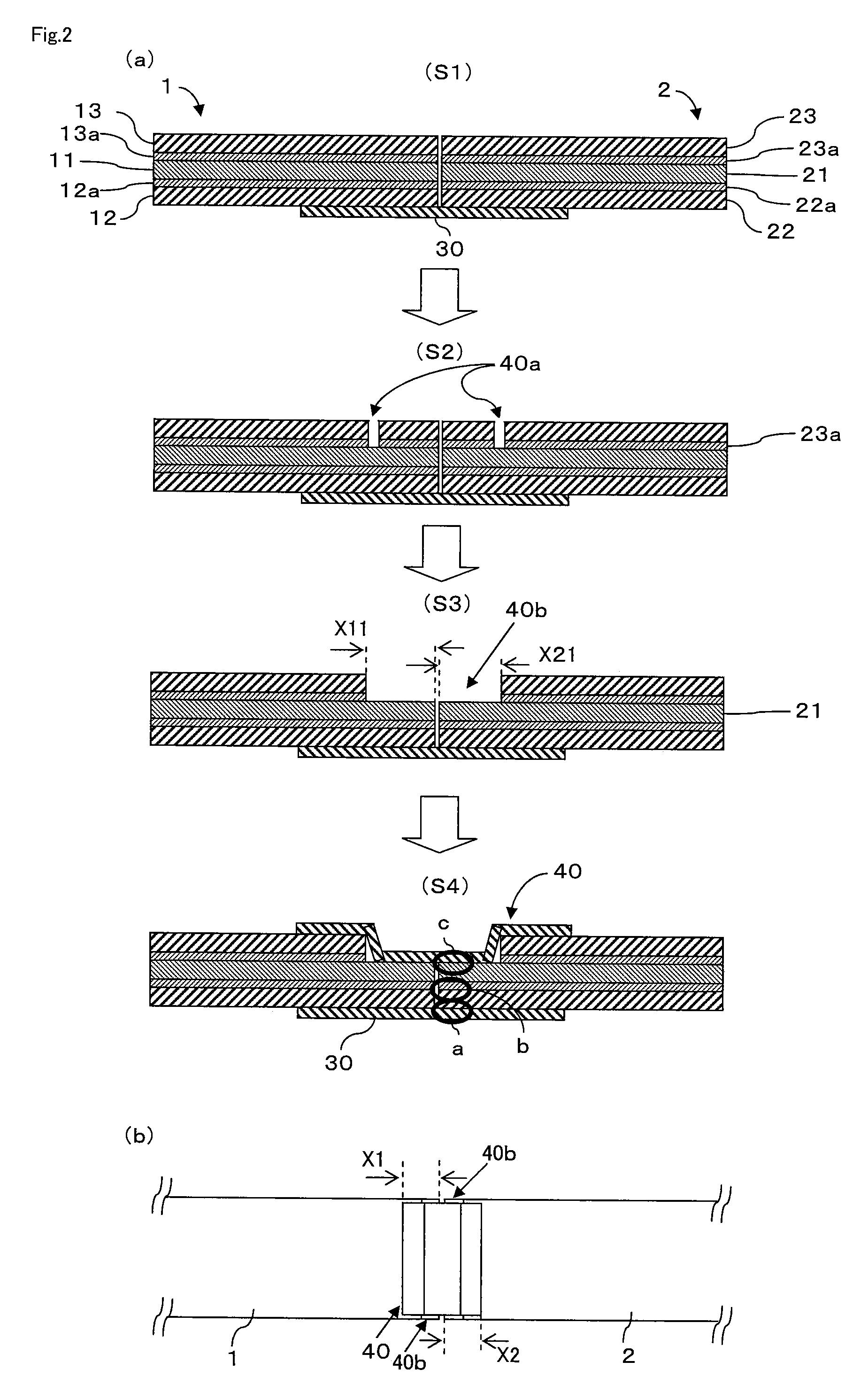
[0061]Embodiment 1 of the invention is described below. In this section, a description is given of how to join the first and second sheet products. FIG. 1 shows a flow chart of the procedure of a joining method. Part (a) of FIG. 2 shows an example of the cross-sectional structure of a joint portion where the first and second sheet products according to the flow chart of FIG. 1 are joined. Part (b) of FIG. 2 shows an exemplary plan view of the joint portion where the first and second sheet products are joined. FIGS. 3 to 6 show other exemplary modes of joint. Each of the first and second sheet products 1 and 2, for the description below, is, but not limited to, a laminated structure including a surface protecting film 13 or 23, a first pressure-sensitive adhesive 13a or 23a, a polarizing plate 11 or 21, a second pressure-sensitive adhesive 12a or 22a, and a release film 12 or 22.

[0062](1) First Joining Step (S1 in FIGS. 1 and 2). The release films 12 and 22 of the first and second sh...

example 1

[0122]A joined sheet product and an optical display unit were manufactured using the above joining method. The sheet product is a laminated structure composed of a surface protecting film (PET film), an acrylic pressure-sensitive adhesive layer, a polarizing plate, an acrylic pressure-sensitive adhesive layer, and a release film (a PET film having a silicone-treated surface to be laminated). The polarizing plate includes a stretched and dyed polyvinyl alcohol film polarizer and triacetylcellulose films provided on both sides of the polarizer with an adhesive interposed therebetween. The joining member used is an adhesive tape (Danpron Tape No. 3041 manufactured by Nitto Denko Corporation). The adhesive tape has a width of 10 cm, a thickness of 70 μm, an adhesive strength of 7 N / 25 mm, a tensile strength of 120 N / 25 mm, and an elongation percentage of 140%. Various test methods are the same as those described above. As shown in FIG. 2, the sheet products were joined to each other wit...


PUM

PropertyMeasurementUnit
thicknessaaaaaaaaaa
thicknessaaaaaaaaaa
glass transition temperatureaaaaaaaaaa

Abstract

The invention is to provide a method for manufacturing a joined sheet product. The method comprising a first joining step including opposing a transverse end face of a first sheet product(1) to a transverse end face of a second sheet product(2) and joining release films of the first and second sheet products with a first joining member(30); a removing step including removing a portion of an intended member including at least a surface protecting member so as to leave at least the release film and a pressure-sensitive adhesive provided on the release film among the constituent members of both or any one of the first and second sheet products(1, 2), wherein the portion has a predetermined length from the transverse end face of the intended member; and a second joining step including providing a second joining member(40) on at least an exposed portion(40b) resulting from the removal of the intended member to join the surface protecting member sides of the first and second sheet products(1, 2).

Description

TECHNICAL FIELD[0001]The invention relates to a method for manufacturing a joined sheet product by joining the end faces of sheet products to each other, and to a joined sheet product in which the end faces of sheet products are joined to each other. The invention also relates to a method for manufacturing an optical display unit, in which the joined sheet product manufactured by the above method or a joined sheet product is used to place an optical member on a substrate.BACKGROUND ART[0002]A description is given below of a manufacturing method including bonding an optical film to an optical display unit (such as a glass substrate unit in which a liquid crystal is sealed). First, a material roll of a long sheet product including an optical film member is manufactured. For example, the “long sheet product” includes a raw material for a polarizing plate for use in a liquid crystal display. For example, a roll of a raw material for a polarizing plate is manufactured by the process desc...

Claims


Application Information

Patent Timeline
Patent Type & Authority Patents(United States)
IPC IPC(8): B29C65/00B32B37/00B32B38/04
CPCB29C65/5042B29C66/022B29C66/1142B29C66/43B29C66/723B29C65/5092B29C65/4825Y10T156/1082B29C66/02241B29C66/1122B29C2793/00B29C2793/0036B29C2793/0054B29K2023/06B29K2023/12B29K2029/00B29K2067/00B29K2995/0034B29L2009/00G02B1/105G02B5/3033G02B5/3083B29C65/505Y10T156/1064Y10T428/1476Y10T156/1075B29C65/5021B29C65/5028B29C65/483Y10T156/1062B29C65/00B29C65/7894B29C66/83411B29C66/72328B29C66/72326B29C66/72321B29C66/71B29C66/0246G02B1/14B29K2081/06B29K2079/08B29K2077/00B29K2069/00B29K2067/003B29K2033/08B29K2029/04B29K2025/06B29K2023/38B29K2023/00B29K2001/00
Inventor YOKOUCHI, TADASHIAMANO, TAKAICHIYURA, TOMOKAZUKITADA, KAZUO
Owner NITTO DENKO CORP
Why Eureka
Try Eureka