Meter system with indicator for vehicle

a technology of meter system and indicator, which is applied in the direction of programme control, instrumentation, dynamo-electric converter control, etc., can solve the problems of inductive noise, buzzer and flasher device may generate noise, and detection error of stopper position

Active Publication Date: 2013-03-19
DENSO CORP
View PDF9 Cites 0 Cited by
  • Summary
  • Abstract
  • Description
  • Claims
  • Application Information

AI Technical Summary

Benefits of technology

[0012]In view of the above-described problem, it is an object of the present disclosure to provide a meter system for a vehicle including an indicator that drives a pointer with using a step motor. A pointing error of a vehicle condition value is reduced, and a user does not feel strangeness of operation of the meter system.
[0014]In the above system, when there is a low possibility that the induction voltage of the field winding is influenced, by the induction noise generated by the flasher semiconductor switch, the voltage detection type zero point stopper position detection operation is performed. Then, the electric angle corresponding to the stopper position detected in the voltage detection type zero point stopper position detection operation is set as the zero point. When there is a high possibility that the induction voltage of the field winding is influenced by the induction noise generated by the flasher semiconductor switch, the zero point return enforcement type zero point stopper position detection operation is performed. Then, the zero point in the zero point return enforcement type zero point stopper position detection operation is set. Thus, the user pays attention to the blink of the flasher, the user does not feel strangeness even if the vibration and abnormal noise of the pointer are generated. Thus, the system is integrated, and the indication of the vehicle speed is improved, and further, the strange feeling of the user is reduced.
[0016]In the above system, when there is a low possibility that the induction voltage of the field winding is influenced by the induction noise generated by the at least one of the flasher semiconductor switch and the buzzer semiconductor switch turns on and off to blink the flasher or to output the sound from the buzzer, the voltage detection type zero point stopper position detection operation is performed. Then, the electric angle corresponding to the stopper position detected in the voltage detection type zero point stopper position detection operation is set as the zero point. When there is a high possibility that the induction voltage of the field winding is influenced by the induction noise generated by the at least one of the flasher semiconductor switch and the buzzer semiconductor switch turns on and off to blink the flasher or to output the sound from the buzzer, the zero point return enforcement type zero point stopper position detection operation is performed. Then, the zero point in the zero point return enforcement type zero point stopper position detection operation is set. Thus, the user pays attention to the blink of the flasher or the output of the sound, the user does not feel strangeness even if the vibration and abnormal noise of the pointer are generated. Thus, the system is integrated, and the indication of the vehicle speed is improved, and further, the strange feeling of the user is reduced.
[0020]Thus, the stopper position is detected by the stopper position detection operation without being affected by the inductive noise generated by the on and off operation of the at least one of the flasher semiconductor switch and the buzzer semiconductor switch, which is disposed adjacent to the field winding. Thus, the driving control unit sets the zero point to be the electric angle corresponding to the stopper position, which has a low possibility to be affected by the inductive noise. Thus, the possibility that an inaccurate zero point becomes the standard of the driving signal is low. The system indicates the vehicle condition value accurately. Accordingly, the system is integrated, and further, indicates the accurate vehicle condition value.
[0022]In the above system, the driving control unit controls the driving signal to be applied to the field winding according to the vehicle condition value with using the zero point as a standard. When the driving signal is controlled with using the zero point as the standard, the pointer rotates to a certain position, which corresponds to the vehicle condition value. The driving control unit executes the zero point stopper position detection operation for detecting the electric angle of the pointer, which stops at the stopper position, with using the inductive voltage. The driving control unit sets the zero point to be equal to the electric angle. The driving control unit detects the inductive voltage at detection time intervals. When the noise generating element generates an inductive noise, the inductive voltage may be affected by the inductive noise so that the inductive voltage is not proper. Thus, the system may not detect accurately that the pointer stops at the stopper position. However, the driving control unit inputs the noise generating signal into the noise generating element so that the generation period of the noise is disposed in the detection interval, in which the detection is not performed. Accordingly, even when the noise generating signal is input from the external element, the driving control unit does not operate the noise generating element immediately. Instead, the driving control unit operates the noise generating element to satisfy a predetermined condition. Since the generation period of the inductive noise is shorter than the detection interval, the control unit controls the generation period in the detection interval, in which the detection is not performed. Thus, the detection time is not disposed in the generation period. For example, when the noise generating signal is input into the noise generating element just after the detection element detects the inductive voltage, the generation period ends before the next detection time. Thus, the time difference between the end of the generation period and the next detection time exists. Thus, the inductive noise is not generated at the detection time. Thus, the inductive voltage is detected without influence of the inductive noise. The zero point stopper position detection operation is executed with using the inductive voltage, which is not affected by the noise. Accordingly, the correct zero point becomes the standard of the driving signal. The vehicle condition value is accurately indicated.

Problems solved by technology

Here, the turn lamp, the hazard lamp the buzzer and the flasher device may generate a noise.
An inductive noise may be generated when the switch turns on and off.
Accordingly, when the semiconductor switch of a flasher function unit functions while the voltage type zero point stopper position detection is executed, detection error of the stopper position may occur because of the inductive noise.
Thus, the stopper position may shift, and therefore, the indicator does not show a correct value of the vehicle condition value.
Specifically, even if the pointer does not contact the stopper, the system mistakes to determine that the pointer contacts and stops at the stopper.
Alternatively, even if the pointer contacts and stops at the stopper, the system mistakes to determine that the pointer rotates.
In this case, visual quality of the meter system is not good, and or abnormal noise may be generated.
Thus, a user may feel strangeness, so that the user may consider that the meter system is broken.
However, the user may feel strangeness since the pointer rotates toward the zero point returning direction although the user does not operate the meter system.
Accordingly, when the user operates the combination lever or when the user switches the hazard lamp on, if the blink of the flasher is delayed, the user may misunderstand that the flasher is broken.

Method used


Image

  • Meter system with indicator for vehicle
  • Meter system with indicator for vehicle
  • Meter system with indicator for vehicle

Examples


first embodiment

[0047](First Embodiment)

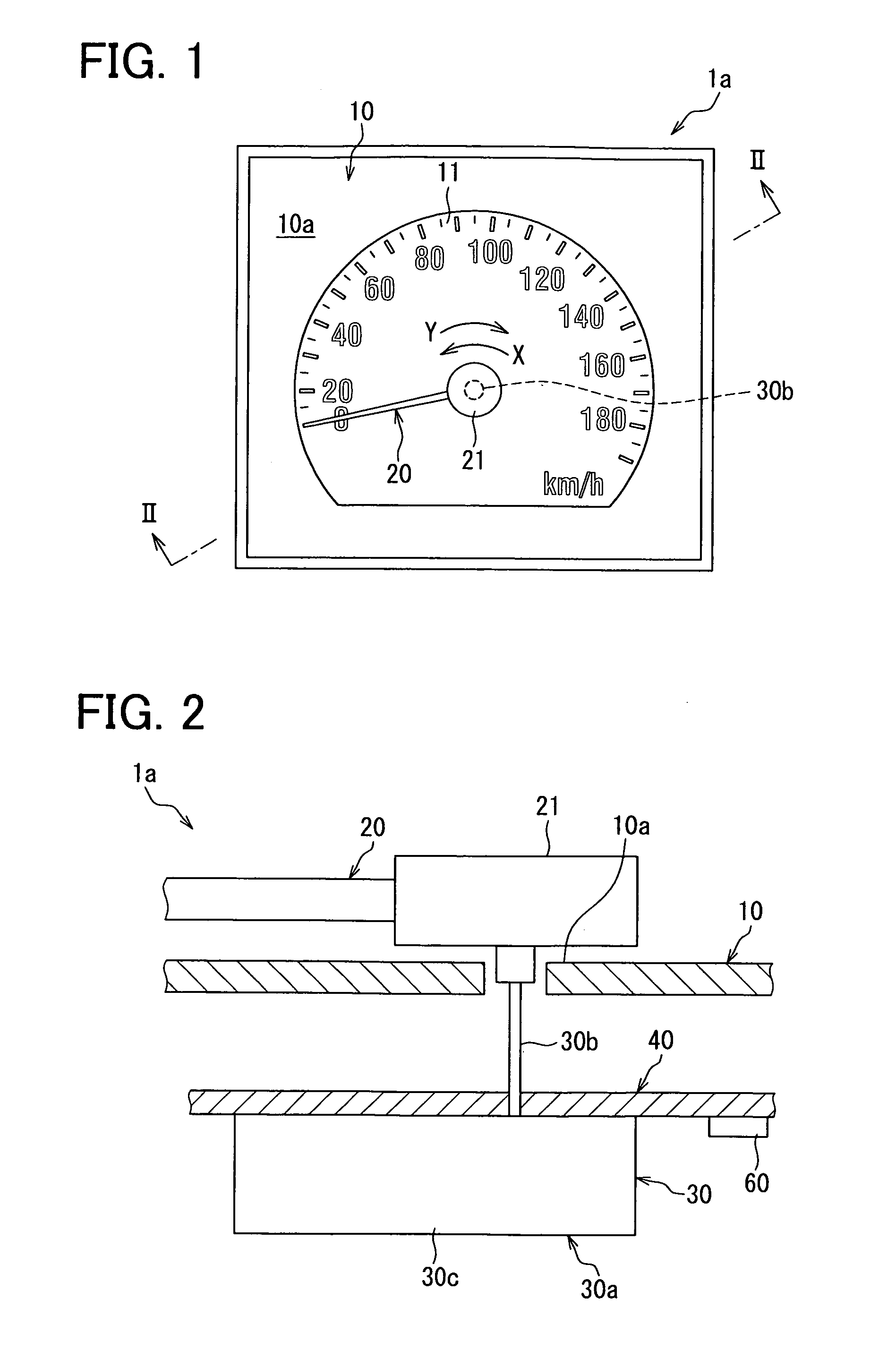
[0048]A meter system 1 according to a first embodiment will be explained with reference to FIGS. 1 to 8. The meter system 1 is arranged as a vehicle speed meter on a front side of a driver seat in a compartment of a vehicle.

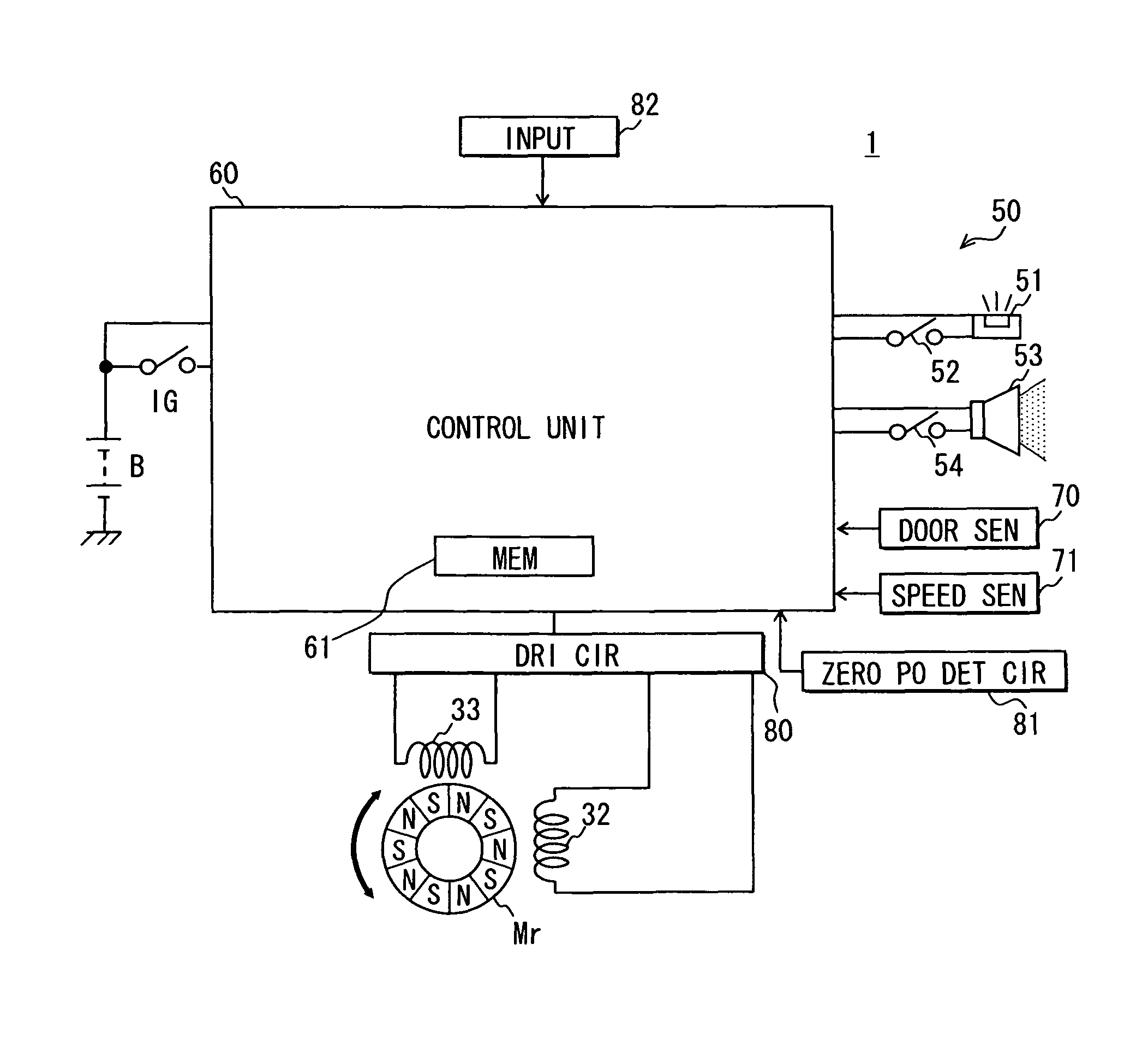
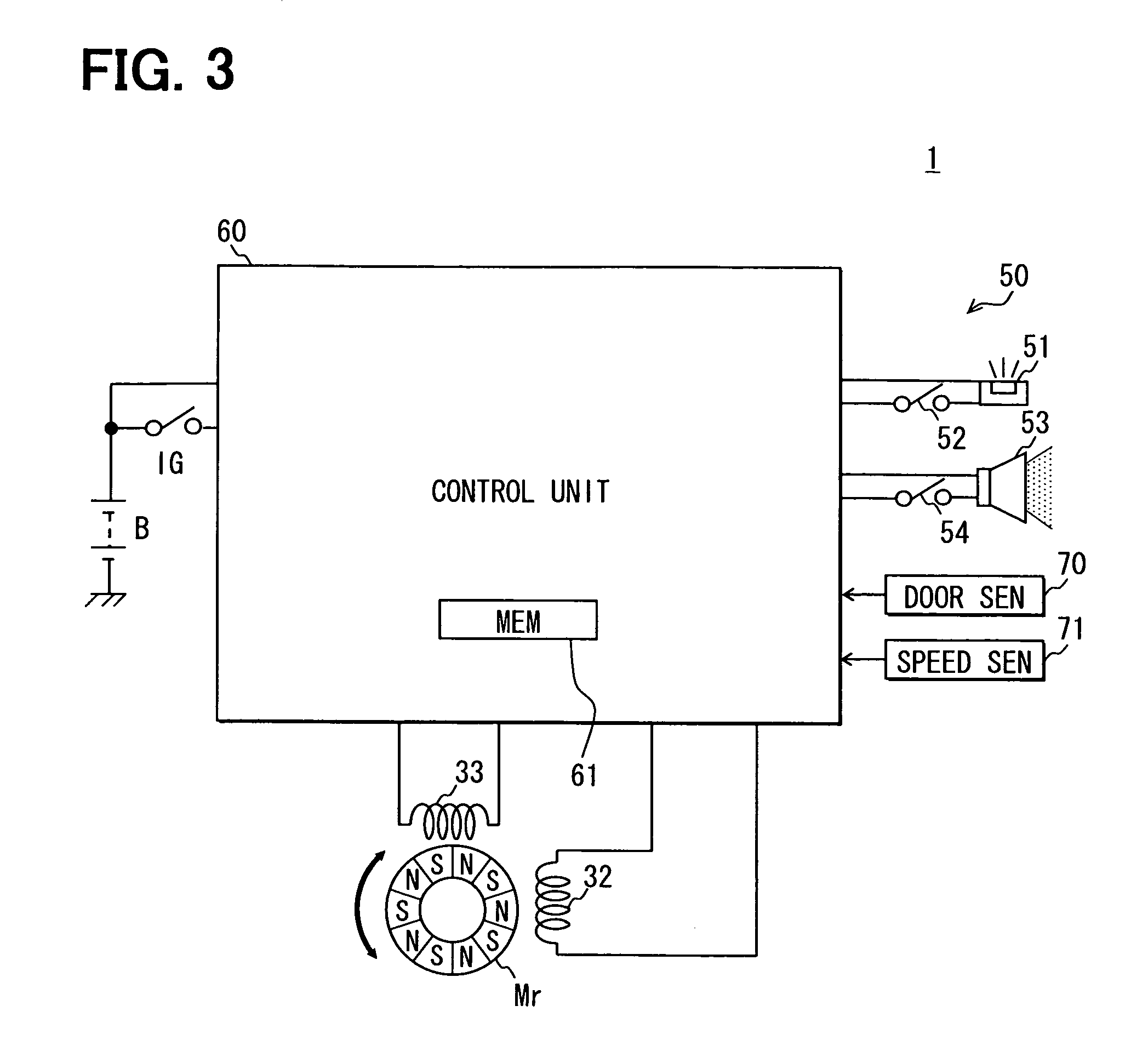
[0049]The meter system 1 includes an indicator 1a for a vehicle. The indicator 1a includes an instrument board 10, a pointer 20, a rotation device 30, a substrate 40 and a control unit 60.

[0050]As shown in FIG. 1, the instrument board 10 has a scale surface 10a, on which a vehicle speed display unit 11 is arranged. The display unit 11 shows a vehicle speed. The scale surface 10a faces the driver seat. The vehicle speed display unit 11 displays multiple vehicle speed values in an arc fashion. The vehicle speed values are, for example, 0 km / h, 20 km / h, 40 km / h and so on. In this embodiment, the zero value equal to 0 km / h is defined as a reference value, and the upper limit of the speed value is 180 km / h. Thus, the vehicle speed value corresp...

second embodiment

[0086](Second Embodiment)

[0087]A meter system according to a second embodiment will be explained with reference to FIGS. 9-11.

[0088]In the first embodiment, the control unit 60 determines in step S11 whether the flasher driving condition is satisfied just after the control unit 60 is activated. Then, the voltage detection type ZPD process in step S16 or the zero point return enforcement type ZPD process in step S14 is performed. In some cases, the flasher driving condition may be satisfied so that the control unit 60 controls the flasher semiconductor switch 52 and the buzzer semiconductor switch 54 to turn on and off while the voltage detection type ZPD process is executed in step S16. In this case, the voltage detection type ZPD process may not be executed under a condition that the possibility of the influence of the inductive noise to the field windings 32, 33 is low.

[0089]In the present embodiment, the control unit 60 executes a meter activation process S2 shown in FIG. 9, whic...

third embodiment

[0114](Third Embodiment)

[0115]In a meter system according to a third embodiment, the control unit 60 includes the micro computer having the memory 61. The control unit 60 is mounted on the substrate 40, as shown in FIG. 2. The memory 61 stores various program for executing a meter activation process S3. The meter activation process S3 includes a stopper position detection operation, a zero point setting operation and a ZPD operation. When the meter activation process S3 is executed, the updated or set zero point θ0, which is the latest value, is stored. The memory 61 stored a memory region for a ZPD flag, which shows execution of the ZPD operation while the control unit 60 is activated.

[0116]The control unit 60 is electrically coupled with the flasher function unit 50, the door sensor 70, the vehicle speed sensor 71, the ignition switch IG and the battery B. The control unit 60 is energized directly from the battery B so that the control unit 60 is activated when the door sensor 70 ...


PUM


Abstract

A meter system includes: an indicator including a pointer, a step motor, a stopper mechanism and a driving controller; and a flasher function unit including a flasher switch, a flasher and a flasher controller. The driving controller has: a stopper position detection operation executing element for executing a pointer moving away operation when a stopper position detection operation executing condition is satisfied and for executing a voltage detection type zero point stopper position detection operation when the executing condition is satisfied, and the flasher switch does not turn on and off, and a zero point return enforcement type zero point stopper position detection operation when the executing condition is satisfied, and the flasher switch turns on and off; a zero point setting element; and an applying element for applying the driving signal having the zero point.

Description

CROSS REFERENCE TO RELATED APPLICATIONS[0001]This application is based on Japanese Patent Applications No. 2009-251188 filed on Oct. 30, 2009, No. 2009-251189 filed on Oct. 30, 2009, No. 2009-251190 filed on Oct. 30, 2009, No. 2009-251191 filed on Oct. 30, 2009, No. 2009-260196 filed on Nov. 13, 2009, No. 2010-76073 filed on Mar. 29, 2010, the disclosures of which are incorporated herein by reference.FIELD OF THE INVENTION[0002]The present invention relates to a meter system for a vehicle including an indicator that drives a pointer with using a step motor.BACKGROUND OF THE INVENTION[0003]Conventionally, an indicator for a vehicle that indicates a vehicle condition value according to a rotation position of a pointer is well known. A driving signal is applied to a field winding of a step motor so that the pointer is rotated. The driving signal is alternately oscillated according to an electric angle. In this indicator, the pointer rotates toward a zero point returning direction so th...

Claims


Application Information

Patent Timeline
Patent Type & Authority Patents(United States)
IPC IPC(8): H02P8/00
CPCB60K37/02G01R7/06G01P1/08B60K2350/302B60K2350/408B60K2370/42B60K2370/698
Inventor NAKANE, HIDEYUKINIWA, MASAAKIMIZUTANI, TAKASHIWATARAI, HIRONORIANJIMA, TERUYUKI
Owner DENSO CORP
Why Eureka
Try Eureka