Ground support equipment tester for laser and tracker systems

a technology of laser tracker and ground support equipment, which is applied in the direction of optical radiation measurement, distance measurement, instruments, etc., can solve the problem that the field cannot be tested presently, and achieve the effect of a very low diffuse coefficient of reflection

Inactive Publication Date: 2013-03-19
DRS NETWORK & IMAGING SYST
View PDF29 Cites 21 Cited by
  • Summary
  • Abstract
  • Description
  • Claims
  • Application Information

AI Technical Summary

Benefits of technology

[0013]Generally, systems, devices, and methods of the present invention are related to test equipment that precisely boresights a camera and laser together in a unit under test (UUT) system. Within the test equipment, a single mirror system receives incoming light from the UUT laser as well as directs output light for a simulated target to the UUT camera. A corner cube reflector—which has the property of reflecting light in the direction from whence it came and being relatively insensitive to all angular and translational motion—reflects a portion of the simulated target light back through the mirror system, and a focus position of this reflected light and the incoming laser light are compared. Based on this position comparison, a field testing crew can adjust the UUT camera and / or laser or issue a simple go / no-go for the UUT.
[0014]Systems, devices, and methods of the present invention are also related to a novel laser safety shroud that uses reflective geometry to prevent a misaligned high-power laser from reflecting back into an adjacent camera in a UUT. A spherical dome enclosure is placed so that a gimbaled UUT's axes of tilt and yaw are positioned at the geometric center of the sphere. The UUT camera, which is usually pointed along the axis of tilt, is protected from both specular reflections that cause optical damage and diffuse (scattering) reflections that cause detector saturation and loss of lock. The direct specular reflections are offset from the UUT camera due to the reflective geometry of the spherical portion. The diffusely scattered power is kept below the UUT camera saturation level by selecting a spherical portion with an inherently very-low diffuse coefficient of reflection.

Problems solved by technology

These presently cannot be tested in the field for fears related to the laser inadvertently firing.

Method used


Image

  • Ground support equipment tester for laser and tracker systems
  • Ground support equipment tester for laser and tracker systems
  • Ground support equipment tester for laser and tracker systems

Examples


Embodiment Construction

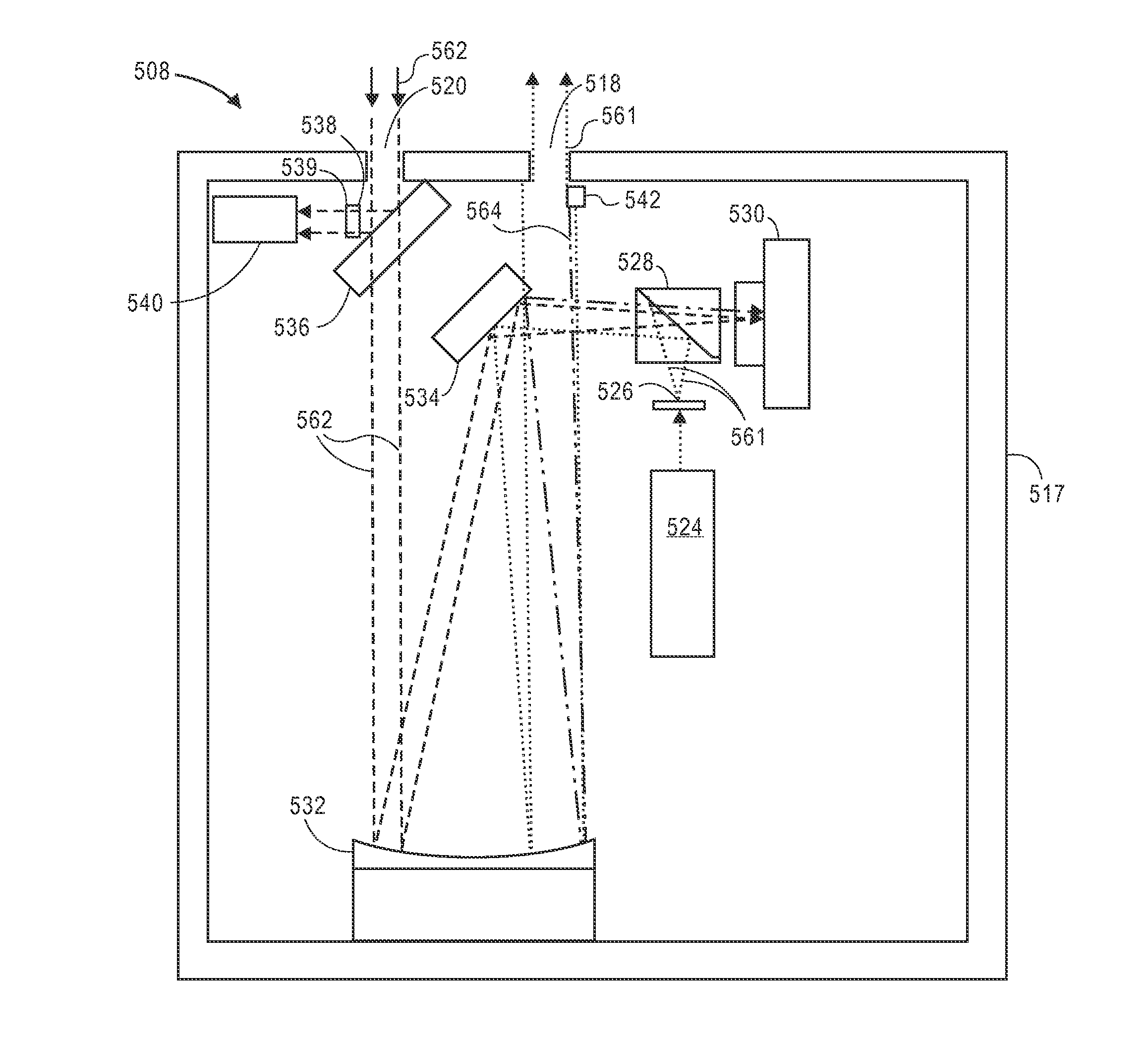
[0032]Generally, real-world IRCM systems should be independently tested or verified in the field. For example, an IRCM system for a helicopter should be tested on a flight line, out in the same weather elements in which the system is supposed to operate. The result of the testing can inform a “go / no go” decision for a mission. Key performance functions for a go / no-go decision can include tracker lock and acquisition, laser fire and average power, and boresight alignment of a laser to a tracker. If the IRCM system fails the flight line test, then it may have a bearing on whether the helicopter is flown in a particular mission. The development of field-support test equipment and methods for use on IRCM systems that are capable of determining a go / no-go verification has become increasingly important as more such advanced integrated imaging and laser systems are being fielded by the U.S. and foreign militaries. Embodiments of the invention can independently test IRCM and like systems.

[0...


PUM


Abstract

Systems, devices, and methods are disclosed for testing the boresight of a gimbaled camera and laser system, such as an infrared countermeasures (IRCM) system, in extreme environments. Light simulating a target is reflected through an optics system to the camera, with a portion of the light reflected back from a corner cube reflector through the optics system as a reference. A laser beam from the laser is received through the same optics system, and a position of the corner cube reflected reference and laser beam are compared in order to determine whether the camera and laser are properly aligned. A spherical shell adapted to position the camera at its geometric center keeps misaligned laser pulses from reflecting back into the camera.

Description

CROSS-REFERENCES TO RELATED APPLICATIONS[0001]Not applicableSTATEMENT AS TO RIGHTS TO INVENTIONS MADE UNDER FEDERALLY SPONSORED RESEARCH OR DEVELOPMENT[0002]Not applicableCOPYRIGHT NOTICE[0003]A portion of the disclosure of this patent document contains material which is subject to copyright protection. The copyright owner has no objection to the facsimile reproduction by anyone of the patent document or the patent disclosure, as it appears in the Patent and Trademark Office patent file or records, but otherwise reserves all copyright rights whatsoever.BACKGROUND[0004]1. Field of the Art[0005]This disclosure is generally related to optics measuring and testing systems, and more specifically to a portable device for the flight-line boresighting of laser and imaging tracker systems. This disclosure is also generally related to laser safety systems, and more specifically to a novel shroud for the safe containment of a high power laser that is adjacent a sensitive imaging system.[0006]2...

Claims


Application Information

Patent Timeline
Patent Type & Authority Patents(United States)
IPC IPC(8): G01B11/26G01J5/02
CPCG01J5/0022F41G1/30G01B11/27G01B11/26G01J2005/0077
Inventor YOUNG, DANIEL D.PANCHAL, DHARMESH G.RAKES, ALAN A.
Owner DRS NETWORK & IMAGING SYST
Why Eureka
Try Eureka