
Oil pump system for vehicle

a technology for oil pumping and vehicles, which is applied in the direction of piston pumps, positive displacement liquid engines, liquid fuel engines, etc., can solve the problems of power loss and decline in the reliability of vane pumps, and achieve the effects of small pulsation, small noise during operation, and constant flow rate characteristics

Active Publication Date: 2013-03-26
JTEKT CORP
View PDF10 Cites 20 Cited by
  • Summary
  • Abstract
  • Description
  • Claims
  • Application Information

AI Technical Summary

Benefits of technology

[0013]The invention has been devised to overcome the above-described problems, and its object is to provide an oil pump system for a vehicle which allows the vehicle to be started smoothly when the engine is started from an idling stop state, without making a large structural change from a conventional oil pump system for a vehicle.
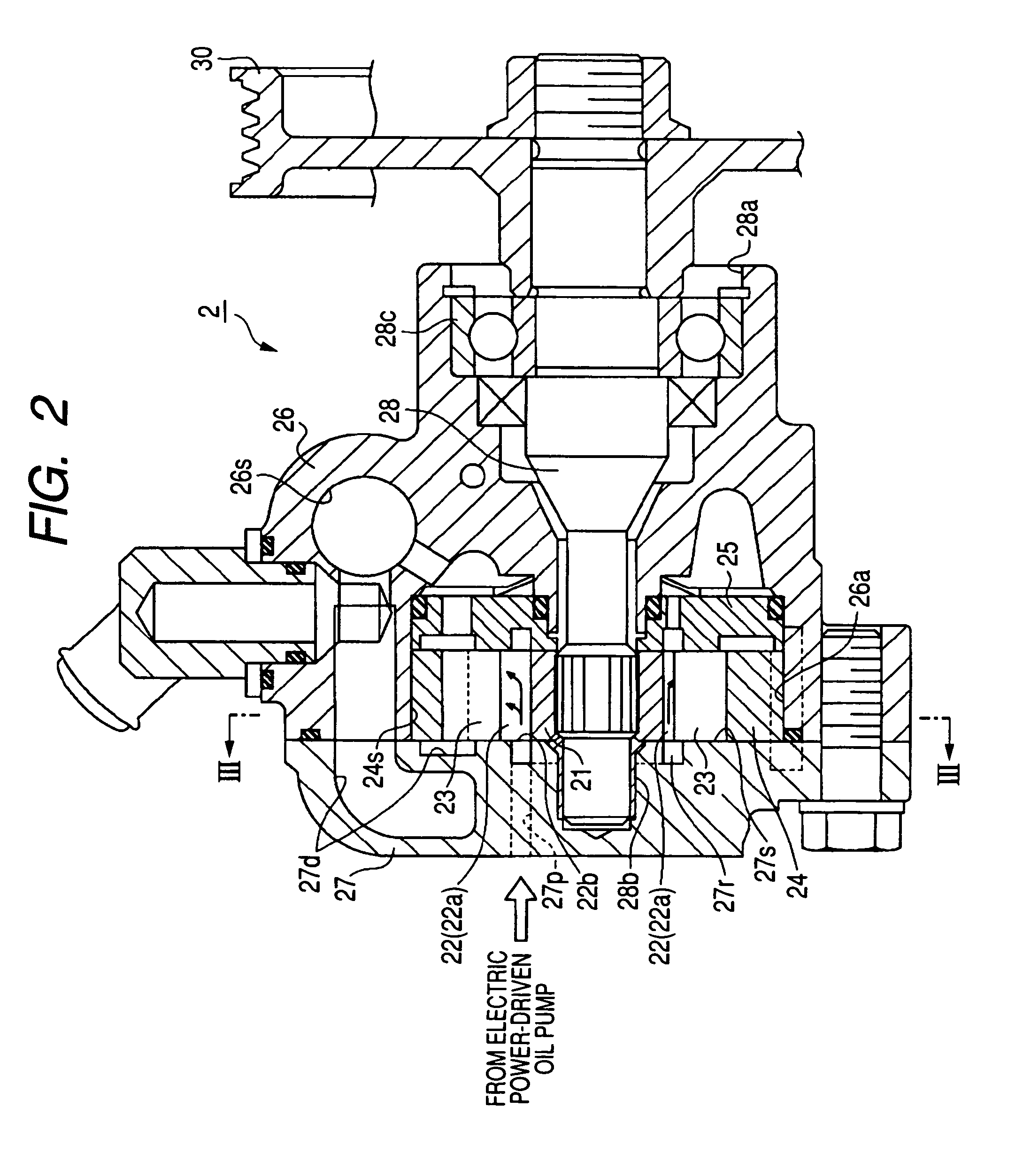
[0017]According to the above-described second aspect of the invention, the check valve, which opens when the hydraulic pressure of the hydraulic fluid delivered from the electric power-driven oil pump exceeds the hydraulic pressure of the hydraulic fluid in the vane accommodating grooves, is interposed in the communication oil passage allowing the discharge portion of the electric power-driven oil pump and the vane accommodating grooves in the vane pump to communicate with each other. For this reason, the check valve is closed by a simple configuration when the hydraulic pressure of the hydraulic fluid in the vane accommodating grooves exceeds the hydraulic pressure of the hydraulic fluid delivered from the electric power-driven oil pump. This avoids the trouble that, for example, a hindrance is caused to the rotation of the rotor in a case where the vane accommodating grooves have assumed an overpressure state, and the pressing force with which the vanes press the cam surface has become excessively large.
[0019]According to the above-described third aspect of the invention, since the electric power-driven oil pump consists of the internal gear pump and the electric motor for rotationally driving the pump, it is possible to realize an oil pump system for a vehicle which excels in the constant flow rate characteristic and in which the pulsation is small, with the result that the noise during operation is small.
[0020]According to the oil pump system for a vehicle in accordance with the invention, it becomes possible to smoothly start the vehicle when the engine is started from an idling stop state, without making a large structural change from a conventional oil pump system for a vehicle.

Problems solved by technology

There have been cases where this power loss constitutes a hindrance to the smooth starting of the automobile.
This also leads to a decline in the reliability of the vane pump as the hydraulic pump 5 for an automobile.

Method used


Image

  • Oil pump system for vehicle
  • Oil pump system for vehicle
  • Oil pump system for vehicle

Examples


Embodiment Construction

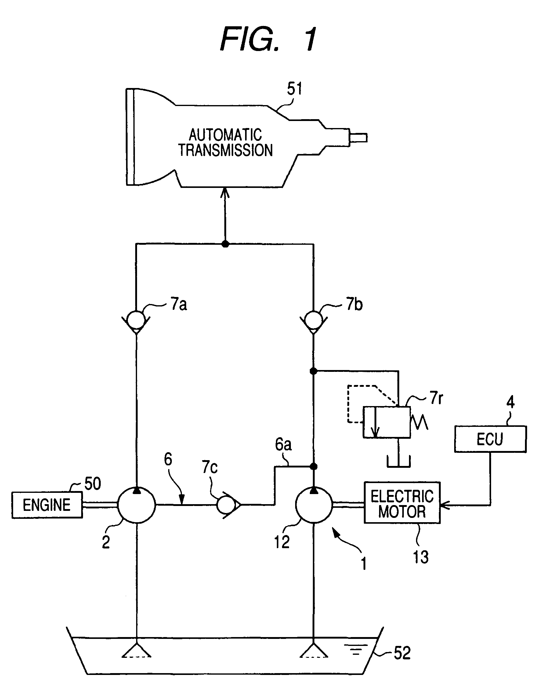
[0028]Referring now to the accompanying drawings, a description will be given of an embodiment of the invention.

[0029]As shown in FIG. 1, the oil pump system for a vehicle in accordance with this embodiment is provided in an automobile having an automatic transmission.

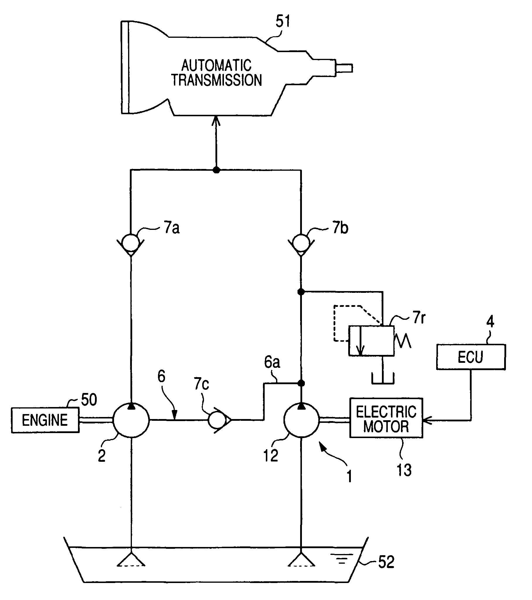
[0030]The oil pump system for a vehicle is comprised of a vane pump (hydraulic pump) 2 which is driven by the torque of a rotating shaft (crankshaft) (not shown) of an engine 50 and is adapted to supply to an automatic transmission 51 a hydraulic fluid for its operation (control) through a piping with a check valve 7a provided therein; and an electric power-driven oil pump (electric power-driven assist pump) 1 which is made up of an internal gear pump (pump) 12 and an electric motor 13 for driving the internal gear pump 12, so as to assist the hydraulic pressure of the hydraulic fluid during an idling stop of the automobile through a piping with a check valve 7b provided therein on the basis of a command from an ECU 4 ...


PUM


Abstract

An oil pump system for a vehicle includes: a vane pump having a plurality of vanes which respectively project retractably from a plurality of vane accommodating grooves provided in a rotor so as to be brought into sliding contact with a cam surface, the vane pump being adapted to supply a hydraulic fluid to an automatic transmission; an electric power-driven oil pump for assisting the hydraulic pressure of the hydraulic fluid during an idling stop of the automobile; and an ECU for controlling its operation. During an idling stop, the hydraulic fluid is fed to the automatic transmission by the operation of the electric power-driven oil pump to assist the hydraulic pressure, while the hydraulic fluid is fed with pressure also to the vane accommodating grooves to press the vanes against the cam surface.

Description

BACKGROUND OF THE INVENTION[0001]1. Field of the Invention[0002]The present invention relates to an oil pump system for a vehicle having a vane pump for supplying a hydraulic fluid to an external hydraulic actuator so as to serve as a hydraulic power source for the hydraulic actuator. More particularly, the present invention concerns an oil pump system for a vehicle having a vane pump for supplying a hydraulic fluid to a hydraulic actuator of an automatic transmission or the like provided in a vehicle such as an automobile, so as to serve as a generating source for the hydraulic actuator.[0003]2. Related Art[0004]A vehicle such as an automobile is provided with an oil pump system for a vehicle which includes a hydraulic pump for supplying a hydraulic fluid to a hydraulic actuator of an automatic transmission or the like provided in a vehicle such as an automobile so as to serve as a generating source of hydraulic pressure required for the hydraulic actuator, as well as a controller ...

Claims


Application Information

Patent Timeline
Patent Type & Authority Patents(United States)
IPC IPC(8): F04B41/06
CPCF04C2/102F04C2/3446F04C14/02F04C14/06F16H61/0031F04C2240/45F16H2312/14
Inventor YOSHINAMI, KOUDI
Owner JTEKT CORP
Learn More