System and method extracting and employing compression heat in biogas treatment plant equipment

a biogas treatment plant and compression heat technology, applied in the field of heat recycling systems, can solve the problems of large heat waste, only partially collected, and large heat loss of compressive gas, and achieve the effect of reducing the overall cycle time and reducing the heat up time for the thermal regeneration cycl

Inactive Publication Date: 2013-04-09
SNAP ENERGY SYST
View PDF11 Cites 3 Cited by
  • Summary
  • Abstract
  • Description
  • Claims
  • Application Information

AI Technical Summary

Benefits of technology

[0010]It is another object of the present invention to provide such a system that enables the operator to easily switch between decontamination (media regeneration) and gas purification (scrubbing) modes.
[0013]The harvesting and conveyance of the heat of compression of the gases to the jacket surrounding the vessel (indirect contact) and simultaneously heating the vessel's interior containing the spent media through the hot gas from another source (direct contact), reduces the heat-up time for the thermal regeneration cycle. This, in turn, reduces the overall cycle time to regenerate the spent media and return the vessel to service in the gas purification mode.

Problems solved by technology

Typically, the heat produced by compressing the gas is either not recovered, or is only partially collected and used by heat exchangers.
Unfortunately, a large portion of the heat is wasted and released into the atmosphere.

Method used


Image

  • System and method extracting and employing compression heat in biogas treatment plant equipment
  • System and method extracting and employing compression heat in biogas treatment plant equipment
  • System and method extracting and employing compression heat in biogas treatment plant equipment

Examples


Embodiment Construction

)

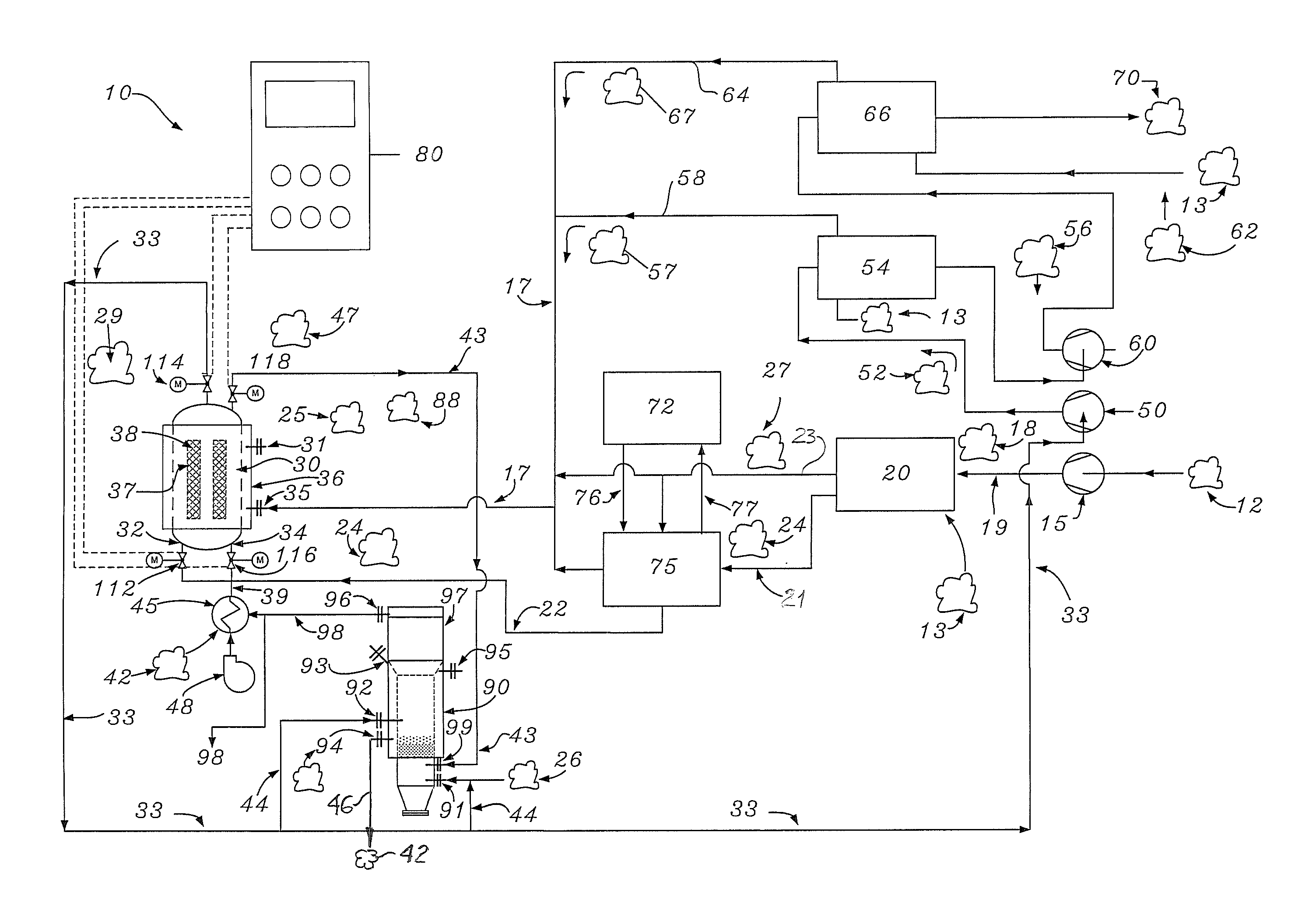
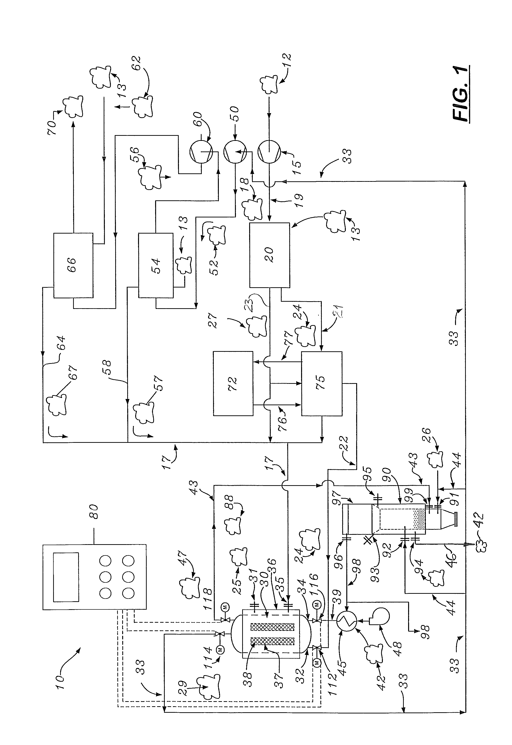
[0018]A biogas system 10 for capturing and conveying the heat from gas compressors to aid or drive the removal of moisture and VOC / organosilicon compounds from biogas 12. The system 10 transmits the heated gases from a plurality of compressors 15, 50, 60 used at different stages of the system 10. Heat from the compressors 15, 50, and 60 is then used to provide uniform and constant temperature control.

[0019]As shown in FIG. 1, low moisture containing raw biogas 12 is delivered to a first stage compressor 15. The raw biogas produced by a landfill or waste water treatment plant digester has moisture that must be removed prior to delivery to the first stage compressor 15. In the first stage compressor, the raw biogas 12 is compressed to a maximum pressure of approximately 100 psig.

[0020]The compressor biogas, designated 18, is hot and delivered via a first conduit 19 to a first stage heat exchanger 20 where heat is removed and cooled. The cooled biogas, now designated 24, from the firs...


PUM

PropertyMeasurementUnit
pressureaaaaaaaaaa
pressureaaaaaaaaaa
pressureaaaaaaaaaa

Abstract

The system and method for recycling and using the heat from compressed gas produced by a biogas treatment plant. The system includes a biogas cleaning stage and a plurality of compression and heat exchanger stages that allows the heat generated by compressed gases to be harvested. After the heat is harvested, it is delivered to a jacketed vessel containing media used to remove contaminants from the biogas. The media inside the jacketed vessel requires regeneration or stripping of harmful VOCs and other contaminants picked up from the biogas. The system also includes an inert gas generator that creates hot inert gas that is delivered to the jacketed vessel that heats the media located therein to remove contaminants. Because the jacket vessel and the media are simultaneously heated, the system's heat-up time is reduced The system also includes a heat exchanger that partially recovers the heat from the inert gas.

Description

[0001]This is a continuation-in-part application based on the utility patent application filed on Jun. 27, 2008 (Ser. No. 12 / 215,633) which claimed the benefit of U.S. Provisional Application No. 60 / 937,587 filed on Jun. 27, 2007 and now U.S. Pat. No. 7,806,964.BACKGROUND OF THE INVENTION[0002]1. Field of the Invention[0003]This invention pertains to heat recycling systems, and more particularly to heat recycling systems used in biogas treatment systems.[0004]2. Description of the Related Art[0005]It is well known that compression of gases produce heat. In systems that generate a large amount of compressed gas, the amount of heat produced can be substantial.[0006]In a landfill or sewage treatment plant, low pressure fuel gases are produced that must be compressed for use with power generation systems, such as reciprocating engine generators, microturbines, and large gas fired turbine generators. Gas compression can encompass 1, 2, or 3 separate stages, depending on the ultimate requ...

Claims


Application Information

Patent Timeline
Patent Type & Authority Patents(United States)
IPC IPC(8): B01D53/04
CPCB01D53/0438C12M47/18B01D2253/102B01D2257/706B01D2257/708B01D2258/05B01D2259/4009B01D2259/40098B01D2259/41B01D2257/80Y02P20/59
Inventor HOWARD, LOWELLWETZEL, JEFFREYDRAKE, RONALD
Owner SNAP ENERGY SYST
Why Eureka
Try Eureka