Surface impedance imaging methods and apparatuses

a technology of impedance imaging and surface impedance, applied in the direction of instruments, measurement devices, scientific instruments, etc., can solve the problems of ms not working in solution phase, ms is not used for practical and routine analysis, and the miniaturization of ms for gas phase analysis is difficult to achiev

Active Publication Date: 2013-04-09
ARIZONA STATE UNIVERSITY
View PDF5 Cites 10 Cited by
  • Summary
  • Abstract
  • Description
  • Claims
  • Application Information

AI Technical Summary

Benefits of technology

[0008]The present invention overcomes deficiencies in the art as described below, and provides a new detection principle that can image or probe local surface impedance of an electrode, and determine the mass to charge ratio of molecules in liquid phase and in microfluidic / nanofluidic devices. In addition to imaging surface impedance of a bare electrode or molecules adsorbed on the electrode in real time, it also allows us to monitor molecular binding processes without using labels, which is particularly useful for biochips and biosensors. Finally, the technique can determine and image the charge of molecules adsorbed on a sensor surface, which can provide additional identity of molecules and new insights into the functions of the molecules.

Problems solved by technology

Atomic force microscopy has been used to probe local capacitance, but it rarely used for practical and routine analysis because it is slow and complicated.
To date, most detection principles detect a change in e.g., mass or current, associated with a molecular binding event but not capable to provide the signature or identity of the target molecule.
However, MS does not work in solution phase, and miniaturization of MS for gas phase analysis faces many challenges.

Method used


Image

  • Surface impedance imaging methods and apparatuses
  • Surface impedance imaging methods and apparatuses
  • Surface impedance imaging methods and apparatuses

Examples


example

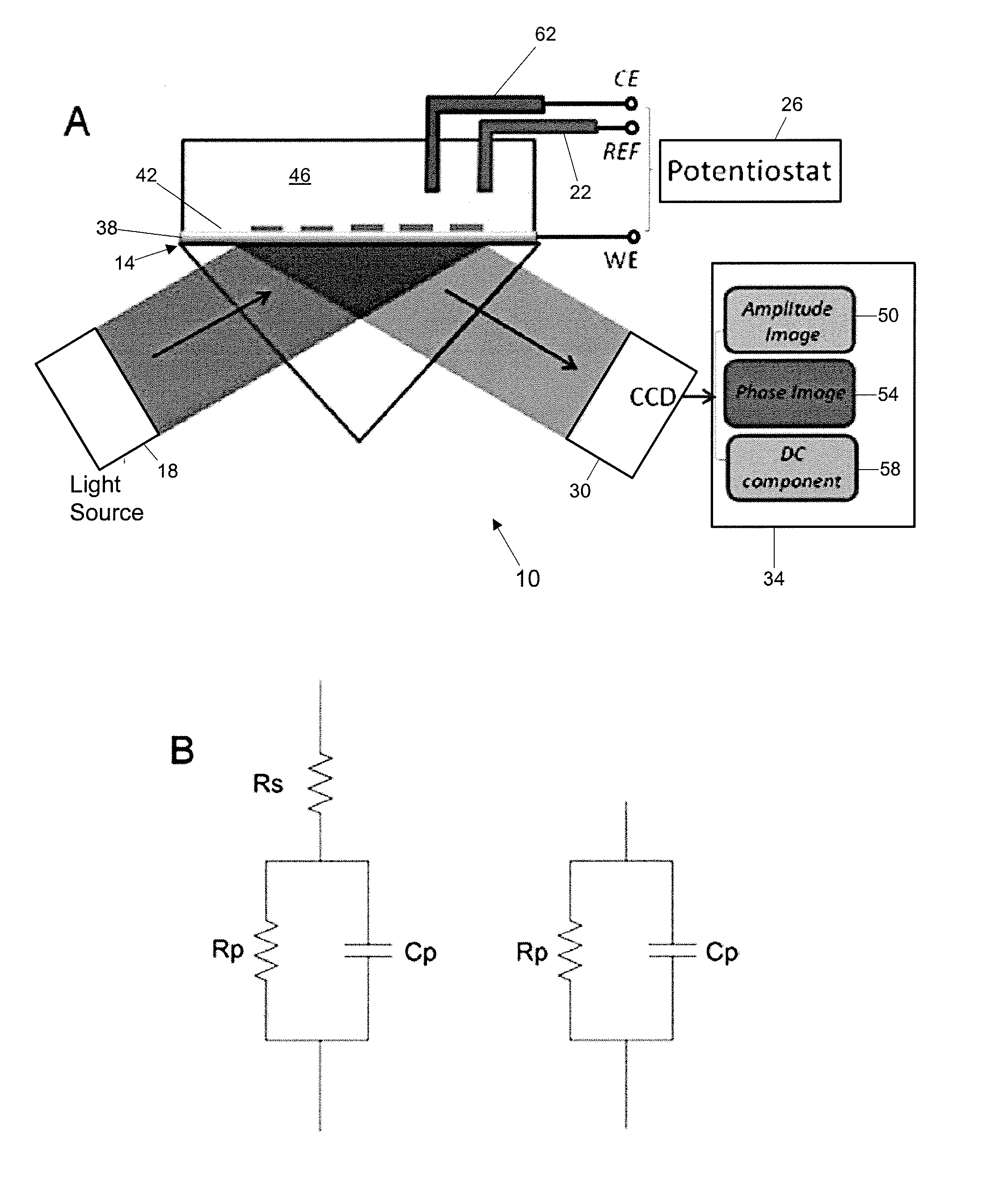
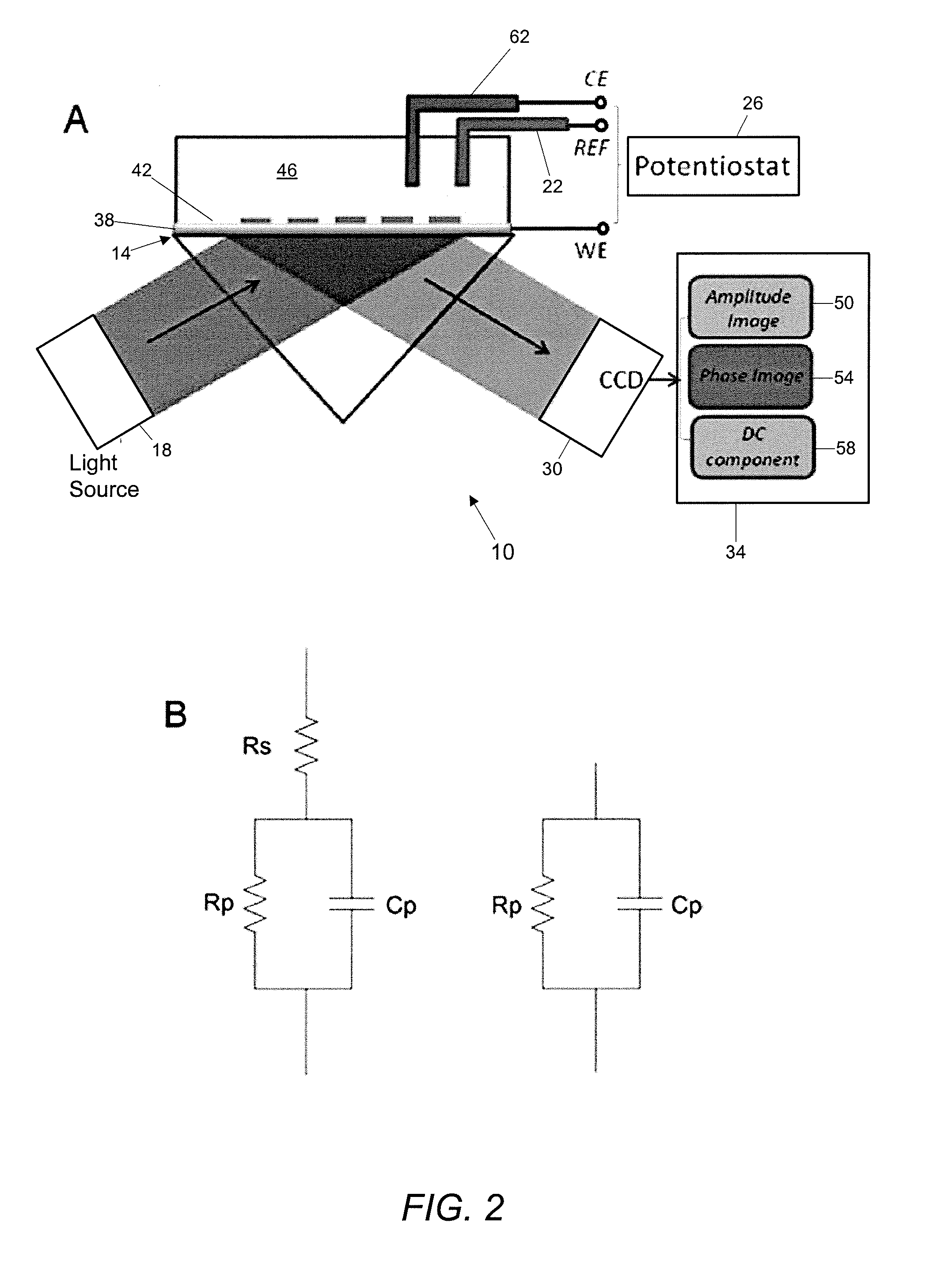
[0060]The SPR imaging setup (apparatus) is based on the widely used Krechmann configuration (FIG. 2A) (Kretschmann, 1971). The optics is comprised of an LED light source (670 nm) (light source 18), collimating lens, prism, imaging optics, polarizer, and a CCD camera (imaging device 30). Initially, the collimated incident beam was adjusted and then fixed at an angle where the reflectivity detected by the CCD is ˜50% of the maximum intensity. A local shift in the resonance angle causes a change in the measured reflectivity which is imaged with the CCD. The SPR image was captured at up to 380 fps, allowing for measurements of the SPR response induced by the applied potential modulation. The images were recorded at a bit depth of 14 bits with a maximum resolution of 320×240 pixels. An image captured signal (square wave) was recorded from the camera to allow for synchronizing (time correlating) the image with the electrochemical current and potential data measured in concert. An electroc...


PUM

PropertyMeasurementUnit
diameteraaaaaaaaaa
resonance angleaaaaaaaaaa
reflectivityaaaaaaaaaa

Abstract

Methods and apparatuses for imaging surface impedance.

Description

CROSS REFERENCES TO RELATED APPLICATIONS[0001]This application is a national phase application under 35 U.S.C. §371 of International Application No. PCT / US2009 / 041648 filed Apr. 24, 2009, which claims priority to U.S. Provisional Patent Application 61 / 048,159, filed Apr. 25, 2008, and to U.S. Provisional Patent Application 61 / 051,242, filed May 7, 2008, all of which are incorporated by reference in their entireties.[0002]The invention was made with United States government support under grant number CHM-0554786 awarded by the National Science Foundation (NSF) and under grant number NIH 1 U01 ES016064-01 awarded by the National Institutes of Health (NIH). The United States government has certain rights in the invention.BACKGROUND OF THE INVENTION[0003]A. Field of the Invention[0004]A new detection principle that can image surface impedance and determine the mass to charge ratio of molecules in liquid phase and in microfluidic / nanofluidic devices.[0005]B. Description of Related Art[00...

Claims


Application Information

Patent Timeline
Patent Type & Authority Patents(United States)
IPC IPC(8): G01N21/55
CPCG01N21/1717G01N21/553G01N2021/1721
Inventor FOLEY, KYLE JAMESTAO, NONGJIAN
Owner ARIZONA STATE UNIVERSITY
Why Eureka
Try Eureka