Method and system for energy-optimized and CO2 emission-optimized iron production

a technology of energy-optimized and emission-optimized iron production, applied in the direction of manufacturing converters, blast furnace components, blast furnaces, etc., can solve the problems of reducing energy consumption and consequently, and achieve the effect of reducing the energy required for producing a unit of quantity of iron and the associated co2 emissions

Inactive Publication Date: 2013-04-16
PRIMETALS TECH AUSTRIA GMBH
View PDF9 Cites 58 Cited by
  • Summary
  • Abstract
  • Description
  • Claims
  • Application Information

AI Technical Summary

Benefits of technology

[0005]It is the object of the present invention to provide a process in which the energy required for producing a unit of quantity of iron and the associated CO2 emissions are reduced. Similarly, an installation for carrying out such a process is to be provided.

Problems solved by technology

Correspondingly, less generator gas has to be produced for the reduction of a certain quantity of iron ore, which in turn reduces the energy consumption and consequently the CO2 emissions per unit of quantity of the product.

Method used


Image

  • Method and system for energy-optimized and CO2 emission-optimized iron production
  • Method and system for energy-optimized and CO2 emission-optimized iron production
  • Method and system for energy-optimized and CO2 emission-optimized iron production

Examples


Embodiment Construction

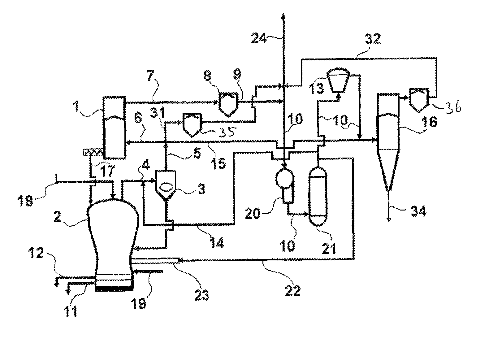
[0041]In FIG. 1, iron ore in lump form, and possibly additions, are filled into the first reduction reactor 1 for iron ore by way of a charging system that is not represented. The iron ore is reduced to sponge iron by reducing gas introduced into the reduction reactor 1 by way of line 6. In the melter gasifier 2 arranged thereunder, a generator gas containing CO and H2 is produced from carbon carriers, which are charged by way of feed line 18, and from gases containing oxygen, which are introduced into the melter gasifier 2 by way of feed line 19. The sponge iron introduced into the melter gasifier by way of conveying line 17 is thereby smelted. Liquid pig iron and liquid slag produced in the melter gasifier 2 are removed from the melter gasifier by way of a tap 11 for pig iron and a tap 12 for slag. The generator gas is discharged from the melter gasifier 2 by way of an outlet line 4, dedusted in a dedusting device 3, in this case a cyclone, and the reducing gas thereby obtained is...


PUM

PropertyMeasurementUnit
volumeaaaaaaaaaa
temperatureaaaaaaaaaa
energyaaaaaaaaaa

Abstract

A process for energy- and emission-optimized iron production and an installation for carrying out the process. A first partial amount of a generator gas produced in a melter gasifier is used as a first reducing gas in a first reduction zone. A second partial amount is fed to at least one further reduction zone as a second reducing gas. In addition, after CO2 scrubbing, a partial amount of top gas removed from the first reduction zone is admixed with the generator gas after the latter leaves the melter gasifier, for cooling the generator gas.

Description

CROSS-REFERENCE TO RELATED APPLICATIONS[0001]The present application is a 35 U.S.C. §§371 national phase conversion of PCT / EP2009 / 057871, filed Jun. 24, 2009 which claims priority of Austrian Application No. A1116 / 2008 filed Jul. 7, 2008, the contents of which are incorporated by reference herein. The PCT International Application was published in the German language.BACKGROUND OF THE INVENTION[0002]The present invention relates to a process for energy- and emission-optimized iron production and to an installation for carrying out the process.[0003]In smelting reduction processes for producing pig iron, a so-called generator gas, which contains CO and H2 as reducing components, is produced from carbon carriers and gas containing oxygen. The generator gas is used as a reducing gas in an assigned reduction reactor. The sponge iron produced in the reduction reactor is charged into the melter gasifier to produce liquid pig iron. Since the generator gas has too high a temperature for the...

Claims


Application Information

Patent Timeline
Patent Type & Authority Patents(United States)
IPC IPC(8): C21B11/08C21B13/14
CPCC21B13/143C21B13/002C21B2100/282C21B2100/44C21B2100/64Y02P10/122Y02P10/134C21B13/14
Inventor BURGLER, THOMASLACKNER, STEPHANMILLNER, ROBERTREDL, REINHARDRUMMER, BERNHARDSCHMID, HERBERTWURM, JOHANNZOBERNIG, ANDREAS
Owner PRIMETALS TECH AUSTRIA GMBH
Why Eureka
Try Eureka