Antenna system and method

a radiation pattern and antenna technology, applied in the field of antenna structures, can solve the problems of inability to affordably and easily manufacture antenna systems in the communication system, and achieve the effect of improving radiation pattern, reducing cost and manufacturability

Active Publication Date: 2013-04-16
UBIQUITI INC
View PDF9 Cites 24 Cited by
  • Summary
  • Abstract
  • Description
  • Claims
  • Application Information

AI Technical Summary

Benefits of technology

[0008]In operation, the shape of the radiator, radome and ground plane operate to effectuate an improved radiation pattern by expanding the radiation pattern of a simple patch antenna. The conical radiator provides for lower cost and manufacturability.

Problems solved by technology

With the advent of low power transmission systems for use in digital networks, communications systems have lacked affordable, easy-to-manufacture antenna systems that provide a wide radiation pattern under adverse conditions.

Method used


Image

  • Antenna system and method
  • Antenna system and method
  • Antenna system and method

Examples


Embodiment Construction

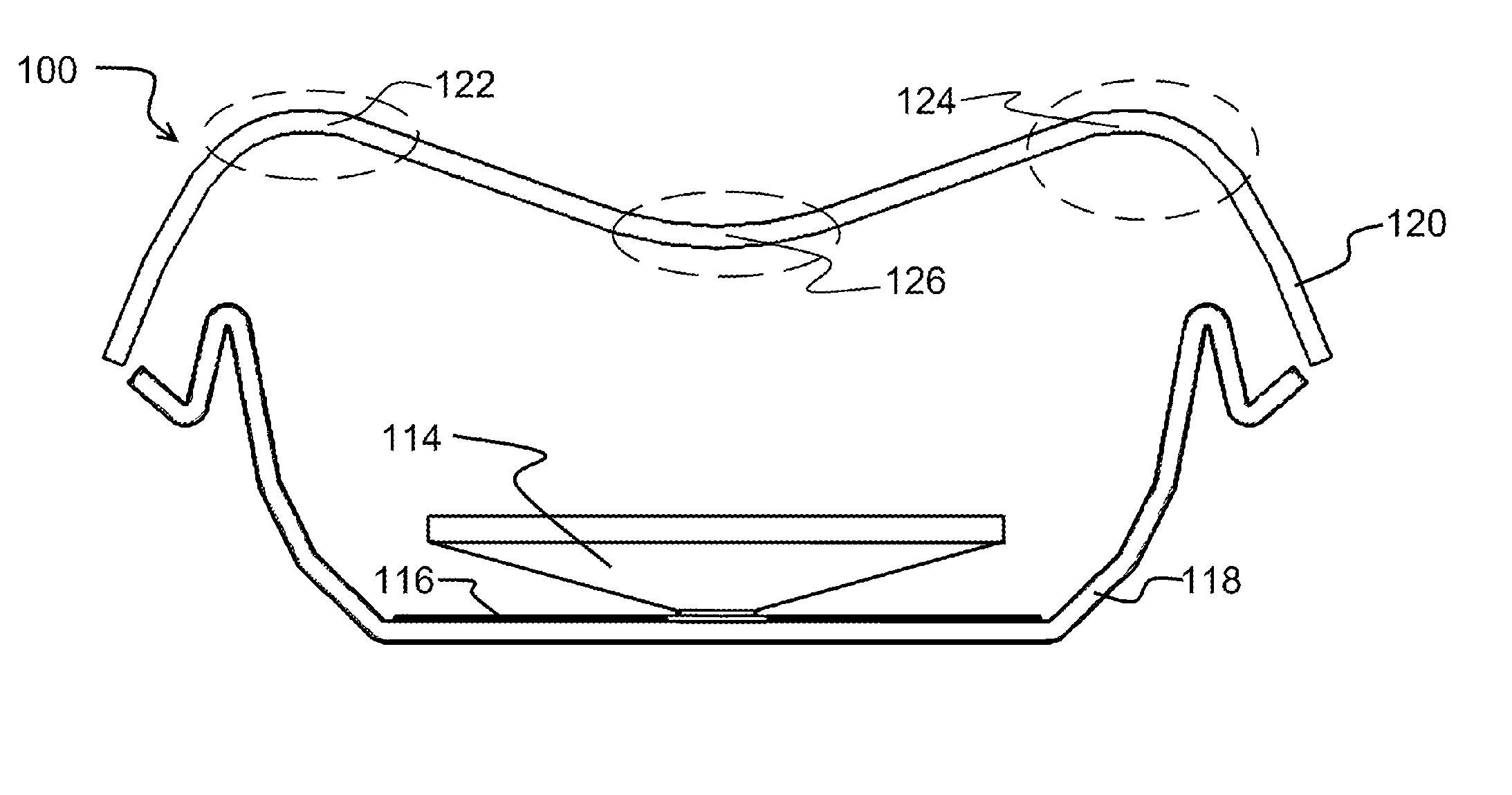
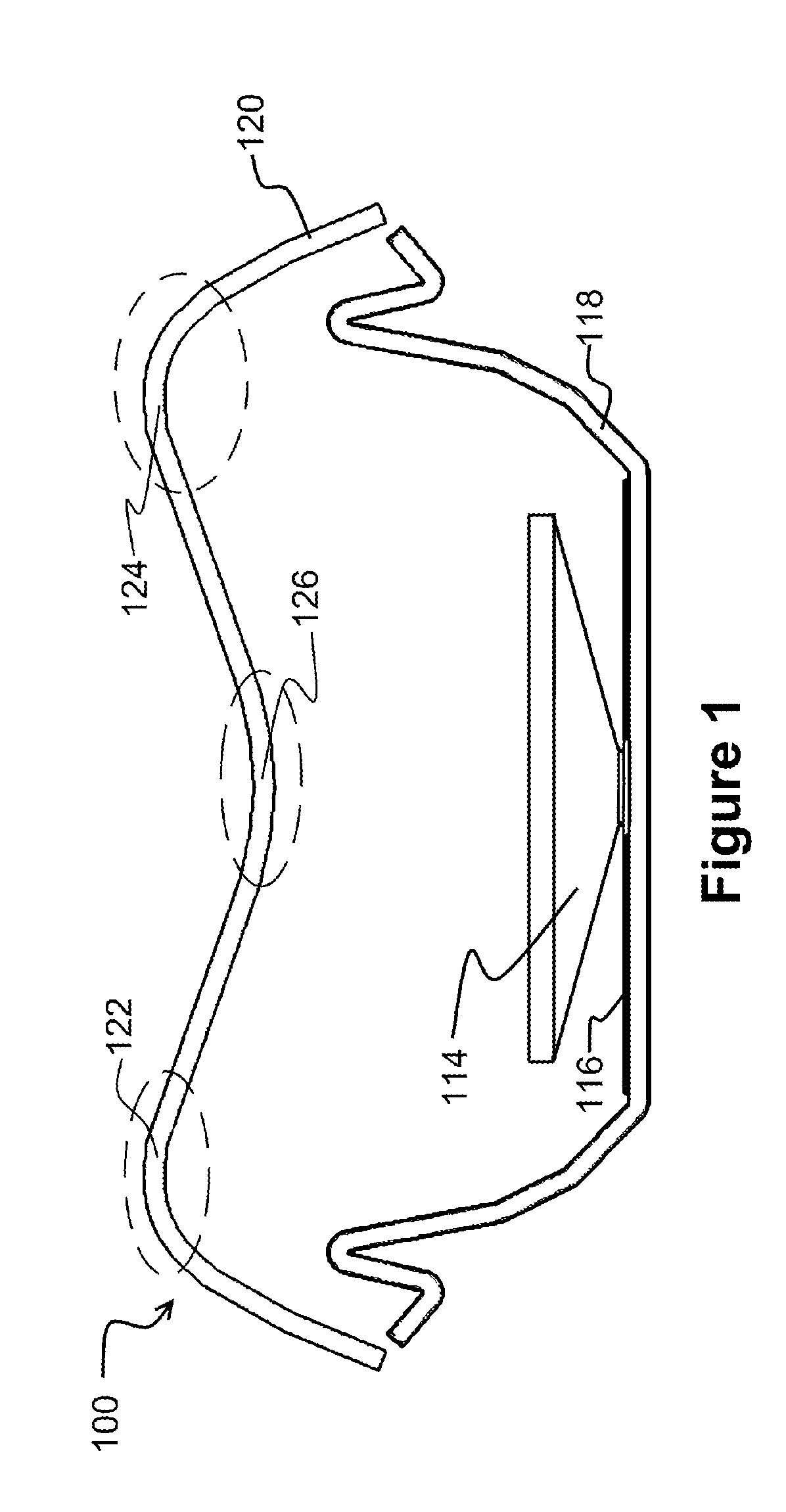
[0035]FIG. 1 illustrates a cut-away view of a conical shaped radiator assembly 100. The radiator assembly 100 includes a substantially conical radiator 114 having a base and a vertex end. In operation the vertex end of the conical radiator 114 would be electrically coupled to a final amplifier of a radio transmitter (not shown) such that the apex would function as an antenna feed point or feed area. The radiator 114 could be impedance matched to the amplifier either by constructing the radiator assembly 100 to predetermined dimensions or through an additional circuit (not shown) tuned to the impedance of the transmission system. When the radio transmitter is transmitting, the radiator 114 would be electrically excited at the frequency of transmission and radiate energy away from the radiator 114.

[0036]The radiator 114 is mounted on a dielectric surface (not shown) having a metallic patch 116. The dielectric surface is mounted on a conductive ground plane 118. The ground plane 118 pr...


PUM

PropertyMeasurementUnit
Operating frequenciesaaaaaaaaaa
carrier frequenciesaaaaaaaaaa

Abstract

A radiator coupled to an antenna patch disposed along a first end of the radiator, said patch disposed on an insulator. A ground plane is connected to the insulator and a radome is disposed opposite a second end of the radiator. The radome may have a region presenting a convex surface towards the radiator, and the radome has a second region presenting a concave surface towards the radiator. The first end of the conical radiator is the apex of the cone. A ground plane is included and a portion of the ground plane is a planar surface and another portion extends away from the planar portion towards the radome. Also disclosed is a method for forming a radiation pattern by shaping the radome to effectuate a predetermined radiation pattern using localized convex and concave surfaces positioned on the radome at different points in relation to the conical radiator.

Description

PRIORITY[0001]This application is a continuation of U.S. patent application Ser. No. 12 / 560,425 entitled “Antenna System and Method” by the same inventor file Sep. 16, 2009 which is incorporated herein as if fully set forth.BACKGROUND[0002]The present invention relates generally to antenna structures and more particularly to a system and method for antenna radiation pattern control in a low cost easy to manufacture antenna system.[0003]Wireless fidelity, referred to as “WiFi” generally describes a wireless communications technique or network that adheres to the specifications developed by the Institute of Electrical and Electronic Engineers (IEEE) for wireless local area networks (LAN). A WiFi device is considered operable with other certified devices using the 802.11 specification of the IEEE. These devices allow wireless communications interfaces between computers and peripheral devices to create a wireless network for facilitating data transfer. This often also includes a connect...

Claims


Application Information

Patent Timeline
Patent Type & Authority Patents(United States)
IPC IPC(8): H01Q1/42
CPCH01Q1/42H01Q1/421H01Q9/0407H01Q13/02H01Q19/106H01Q21/06H01Q1/48H01Q19/10H01Q19/00Y10T29/49016H01Q1/2291H01Q1/246H01Q1/36
Inventor SANFORD, JOHN R.
Owner UBIQUITI INC
Why Eureka
Try Eureka