
Automated closed loop flowback and separation system

a closed loop, flowback technology, applied in the direction of drilling casings, drilling pipes, borehole/well accessories, etc., can solve the problems of air presenting a safety hazard, high cost of nitrogen purchase or extraction from the atmosphere, and release into the atmospher

Inactive Publication Date: 2013-04-23
CANADIAN FRACMASTER
View PDF38 Cites 60 Cited by
  • Summary
  • Abstract
  • Description
  • Claims
  • Application Information

AI Technical Summary

Benefits of technology

The invention has several advantages over existing systems. It can calculate the equivalent choke diameter and adjust it automatically or remotely to compensate for wear and tear without having to open or close valves. It can handle large slugs of liquid and closed loop flowback operations without releasing them into the environment. The control valves can be controlled automatically or remotely, so personnel do not have to be exposed to high pressure piping. The invention also has a four-phase separation system and can communicate historical and current process data to a remote location and control the system from there.

Problems solved by technology

Nitrogen is expensive to purchase or extract from the atmosphere for use in the operation.
Air presents a safety hazard due to the risk of introducing a combustible mixture into the well bore.
The use of natural gas requires purchasing the gas and then burning it in a flare at the end of the operation, resulting in a release to the atmosphere.
Additionally, the process of controlling the rate of the flowback presents safety hazards due to the difficulty of monitoring the impact of the abrasive and corrosive fluids on the choke restriction and process piping.
The potential for a washout of the choke or process piping presents risk for injury and environmental release.

Method used


Image

  • Automated closed loop flowback and separation system
  • Automated closed loop flowback and separation system
  • Automated closed loop flowback and separation system

Examples


Embodiment Construction

Best Modes for Carrying Out the Invention

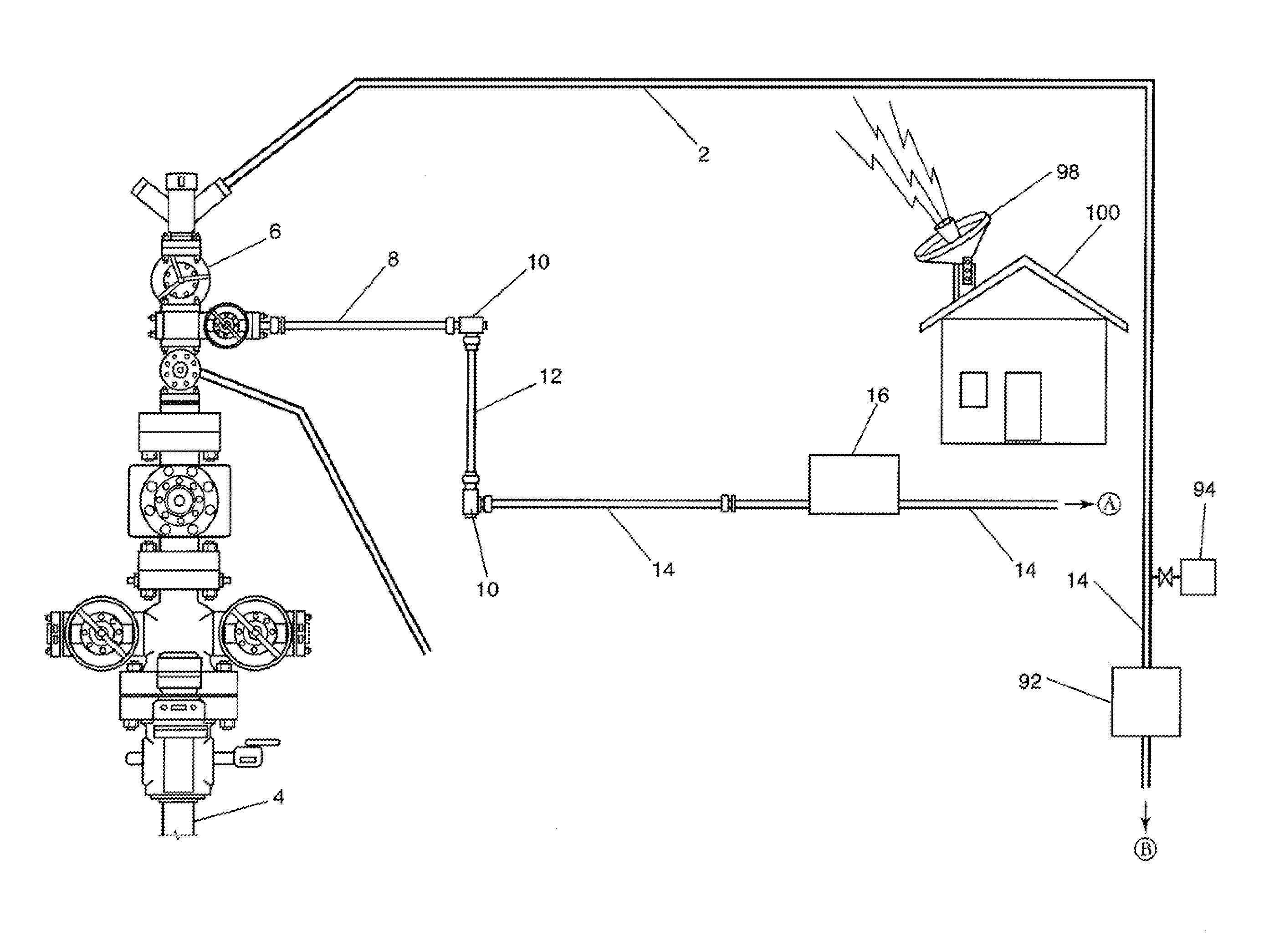
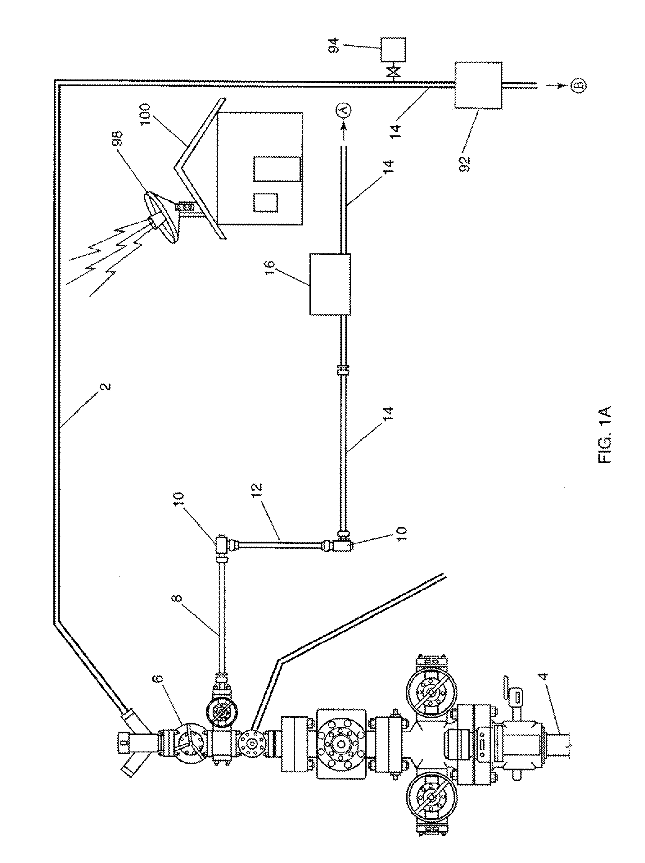
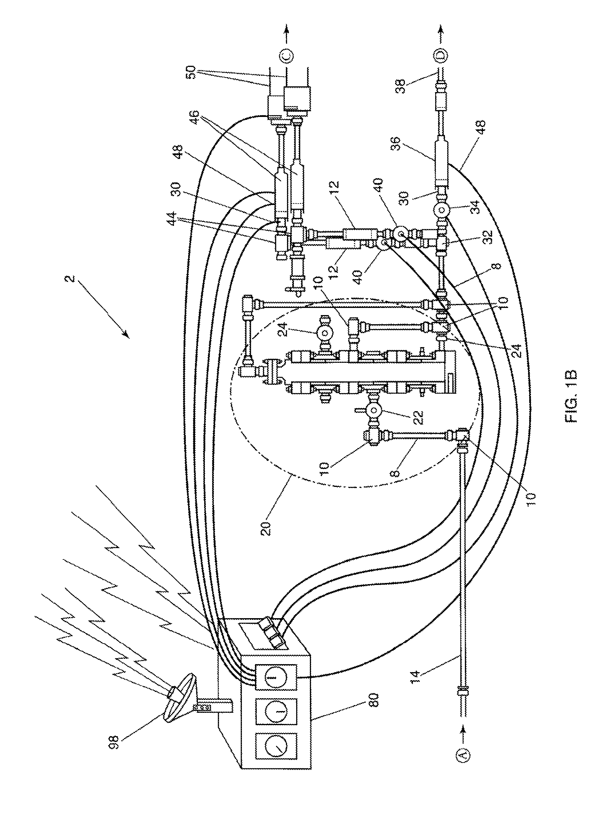
[0022]A choke or choke restriction is defined as a component or method of restricting flow. A choked flow condition is a condition, that due to the size of the restriction, no matter how much you increase the upstream pressure or decrease the downstream pressure, no additional volume of fluid can flow. As used for this disclosure, a choke restriction is used to prevent the pressure in the well bore from wildly flowing free and ruining the well. The well is brought “on-line” in a slow controlled manner by slowly increasing the diameter of the choke restriction. When a choke restriction is used, the flow regime exiting the choke restriction is highly turbulent, causing erosion of the choke restriction and downstream components. By monitoring the pressure differential across the choke, and comparing to the flow rate measured by the outlet flow meters, one can calculate an equivalent choke diameter and determine how much it has eroded. A sensor t...


PUM


Abstract

An automated closed loop flowback and separation system that allows automated control and remote operation of a flowback operation from a safe distance without any fluid or gas release to the atmosphere. Four-phase separation tanks allow the transport gas, well bore cuttings, produced oil, and produced water to be automatically separated and transported through process piping for reuse or sale, eliminating the need for auxiliary equipment. Flow measurement instruments, pressure transmitters, and level transmitters work in conjunction with an automated blast choke to send data to a programmable logic controller for use in calculating the erosion status of the choke restriction and adjusting the choke to compensate. The programmable logic controller works with a touch-screen or similar human-machine interface to allow remote monitoring and control or automated control of the system. The automated blast choke can vary the choke restriction opening based on the pressure differential and flow rate conditions.

Description

CROSS-REFERENCE TO RELATED APPLICATIONS[0001]This application claims priority to Provisional Application Ser. No. 61 / 173,768, filed on Apr. 29, 2009 entitled “Flowback Tank System” and also to Provisional Application Ser. No. 61 / 174,127, filed on Apr. 30, 2009, entitled “Flowback Tank System” and is a continuation-in-part to co-pending patent application Ser. No. 12 / 609,252, entitled “Automated Flowback and Information System” filed on Oct. 30, 2009, which is a Divisional Patent Application of Ser. No. 11 / 731,382 filed Mar. 29, 2007, now U.S. Pat. No. 7,621,324, entitled “Automated Flowback and Information System”, all owned by the Applicant hereof and hereby expressly incorporated by reference herein.BACKGROUND OF THE INVENTION[0002]1. Field of the Invention (Technical Field)[0003]The presently claimed invention relates to oil and gas well servicing and more particularly to a flowback and separation system for controlling the flow of fluids into the separation system, the separatio...

Claims


Application Information

Patent Timeline
Patent Type & Authority Patents(United States)
IPC IPC(8): E21B43/34E21B43/12
CPCE21B34/00E21B37/00E21B43/12E21B43/25E21B43/34E21B43/35E21B2200/02E21B34/025
Inventor ATENCIO, DON
Owner CANADIAN FRACMASTER
Learn More