Optical disk drive

a technology of optical disk drive and optical disk drive, which is applied in the direction of digital signal error detection/correction, instruments, recording signal processing, etc., can solve the problems of deteriorating the quality of a regenerated signal during data regeneration, servo failure to perform tracking, and inability to perform retry during data recording operation, etc., to achieve the effect of ensuring recording quality, reducing unwanted current consumption, and saving power

Inactive Publication Date: 2013-04-23
TEAC CORP
View PDF4 Cites 0 Cited by
  • Summary
  • Abstract
  • Description
  • Claims
  • Application Information

AI Technical Summary

Benefits of technology

[0015]The present invention provides an optical disk drive that can pursue power saving by reducing unwanted current consumption of a tracking actuator or a focus actuator and simultaneously assure recording quality even in a data recording period.

Problems solved by technology

However, when there is a defect in an optical disk that exceeds the limit voltage; for instance, a local surface run-out or a decenter, the servo fails to perform tracking.
A residual servo track eventually becomes large, which in turn deteriorates quality of a regenerated signal during data regeneration.
In the meantime, when a defect, such as that mentioned above, exists in the optical disk, a retry cannot be performed during data recording operation, whereupon a write error immediately occurs.
In particular, in a write once optical disk, such as a CD-R and a DVD-R, a retry of writing operation is impossible to perform; therefore, a write error immediately occurs at that point in time.

Method used


Image

  • Optical disk drive
  • Optical disk drive
  • Optical disk drive

Examples


Embodiment Construction

[0031]An embodiment of the preset invention is now described hereunder by reference to the accompanying drawings.

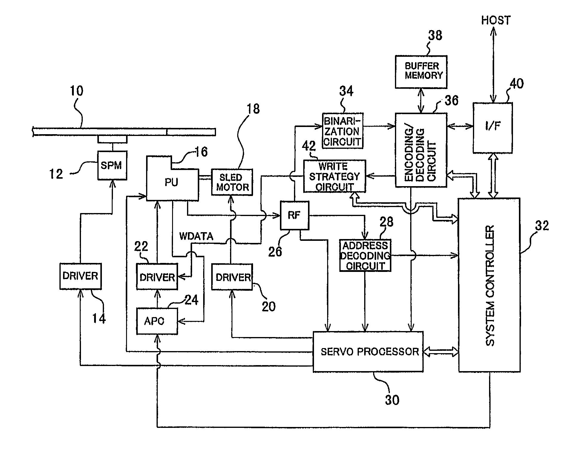
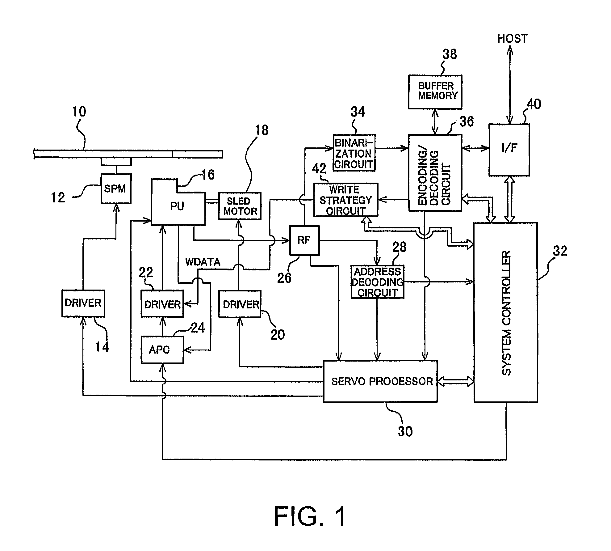
[0032]FIG. 1 shows an overall configuration of an optical disk drive of an embodiment. An optical disk 10 capable of recording and regenerating data, such as a CD-R / RW disk, a DVD-R / RW disk, a DVD-RAM disk, and a Blu-ray disk, is driven by a spindle motor (SPM) 12. The spindle motor SPM 12 is driven by a driver 14, and the driver 14 is servo-controlled so as to achieve a desired rotational speed.

[0033]An optical pickup 16 includes a laser diode (LD) for irradiating the optical disk 10 with a laser beam and a photodetector (PD) that receives light reflected from the optical disk 10 and that converts the thus-received light into an electric signal. The optical pickup 16 is disposed opposite the optical disk 10. The optical pickup 16 is driven by a sled motor 18 made up of a stepping motor, in a radial direction of the optical disk 10. The sled motor 18 is driven by a driver...


PUM

PropertyMeasurementUnit
frequencyaaaaaaaaaa
rotational speedaaaaaaaaaa
drive forceaaaaaaaaaa

Abstract

There is provided an optical disk drive that pursues power saving and simultaneously assures data recording quality. A servo processor of the optical disk drive has a low frequency equalizer, a high frequency equalizer, a limiter, and an adder. A limit voltage value of the limiter is set by means of a control command from a system controller. The limit voltage value is set so as to become greater during a data recording period than in a data regeneration period. An output from the adder is supplied as a tracking drive signal to a tracking actuator or as a focus drive signal to a focus actuator.

Description

[0001]This application claims priority to Japanese Patent Application No. 2010-054442, filed on Mar. 11, 2010, which is incorporated herein by reference in its entirety.BACKGROUND[0002]1. Technical Field[0003]The present invention relates to an optical disk drive and, more particularly, to a tracking servo method employing a tracking error signal and a focus servo method employing a focus error signal.[0004]2. Related Art[0005]In relation to a tracking servo apparatus that lets; for instance, a beam spot, follow a target track, a hitherto known configuration includes supplying a tracking error signal to low frequency compensation means and high frequency compensation means, letting the low frequency compensation means make a correction to a low frequency component of the tracking error signal and the high frequency compensation means make a correction to a high frequency component of the same, adding the thus-corrected signals to each other, and supplying a resultant signal to drive...

Claims


Application Information

Patent Timeline
Patent Type & Authority Patents(United States)
IPC IPC(8): G11B20/18G11B5/55G11B20/10
CPCG11B7/094
Inventor OTSUKA, YOSHIYUKIMIYARA, TATSUO
Owner TEAC CORP
Why Eureka
Try Eureka