
Multi-rate multi-receiver multi-response aggregation

a multi-receiver, multi-response technology, applied in multiplex communication, furniture parts, high-level techniques, etc., can solve the problems of lack of adequate information to schedule multiple responses, limited use, and inability to support multiple responses, so as to broaden the scope of applications, support the multi-response aspect of an mrmrmra, and improve the use of existing aggregation technology.

Active Publication Date: 2013-04-30
CISCO TECH INC
View PDF7 Cites 3 Cited by
  • Summary
  • Abstract
  • Description
  • Claims
  • Application Information

AI Technical Summary

Benefits of technology

This patent describes a method and system for combining two existing technologies called MRMRA and MMRA to create a new technology called MRMRMRA. This new technology has a broader scope of applications and benefits from both MRMRA and MMRA. It also requires less overhead and has low latency, which is beneficial for applications that require fast data transfer. Overall, this new technology allows for better utilization of network resources and improved performance for latency-sensitive applications.

Problems solved by technology

However, MMRA's lack of support for immediate responses makes its use very limited, especially for latency sensitive applications such as WVoIP.
MMRA does not support multiple responses mainly for two reasons.
First, an initiator for an MMRA does not know, in general, how long the bursting will last, so it lacks adequate information to schedule multiple responses.
Second, the MMRA approach lacks a protection mechanism to protect the multi-responses from legacy nodes or hidden nodes.
Moreover, scheduling multiple responses after the end of bursting is not favorable because it introduces excessive latency into the responses, which can be intolerable for latency sensitive applications, such as WVoIP in an enterprise environment, making QoS requirements hard to meet.

Method used


Image

  • Multi-rate multi-receiver multi-response aggregation
  • Multi-rate multi-receiver multi-response aggregation
  • Multi-rate multi-receiver multi-response aggregation

Examples


Embodiment Construction

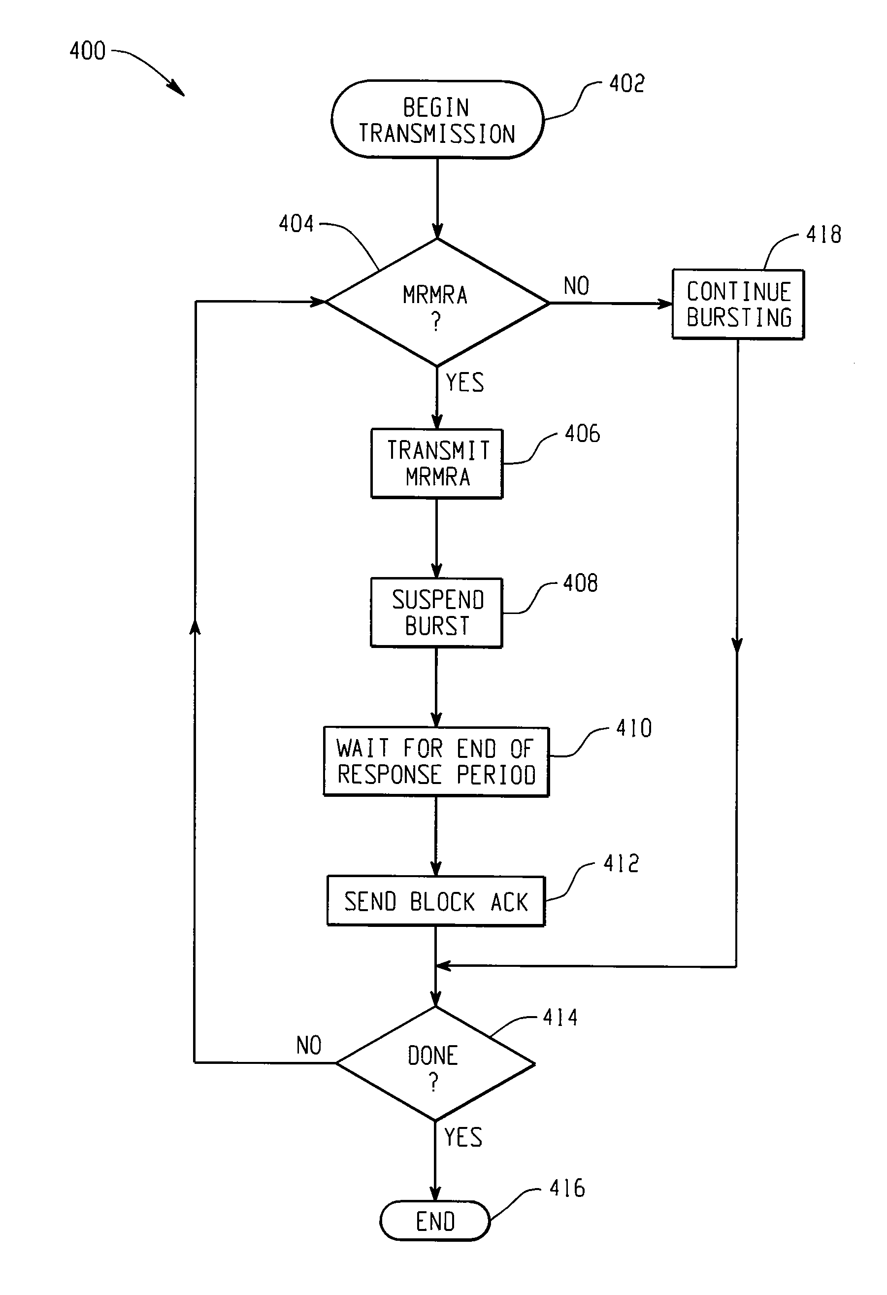
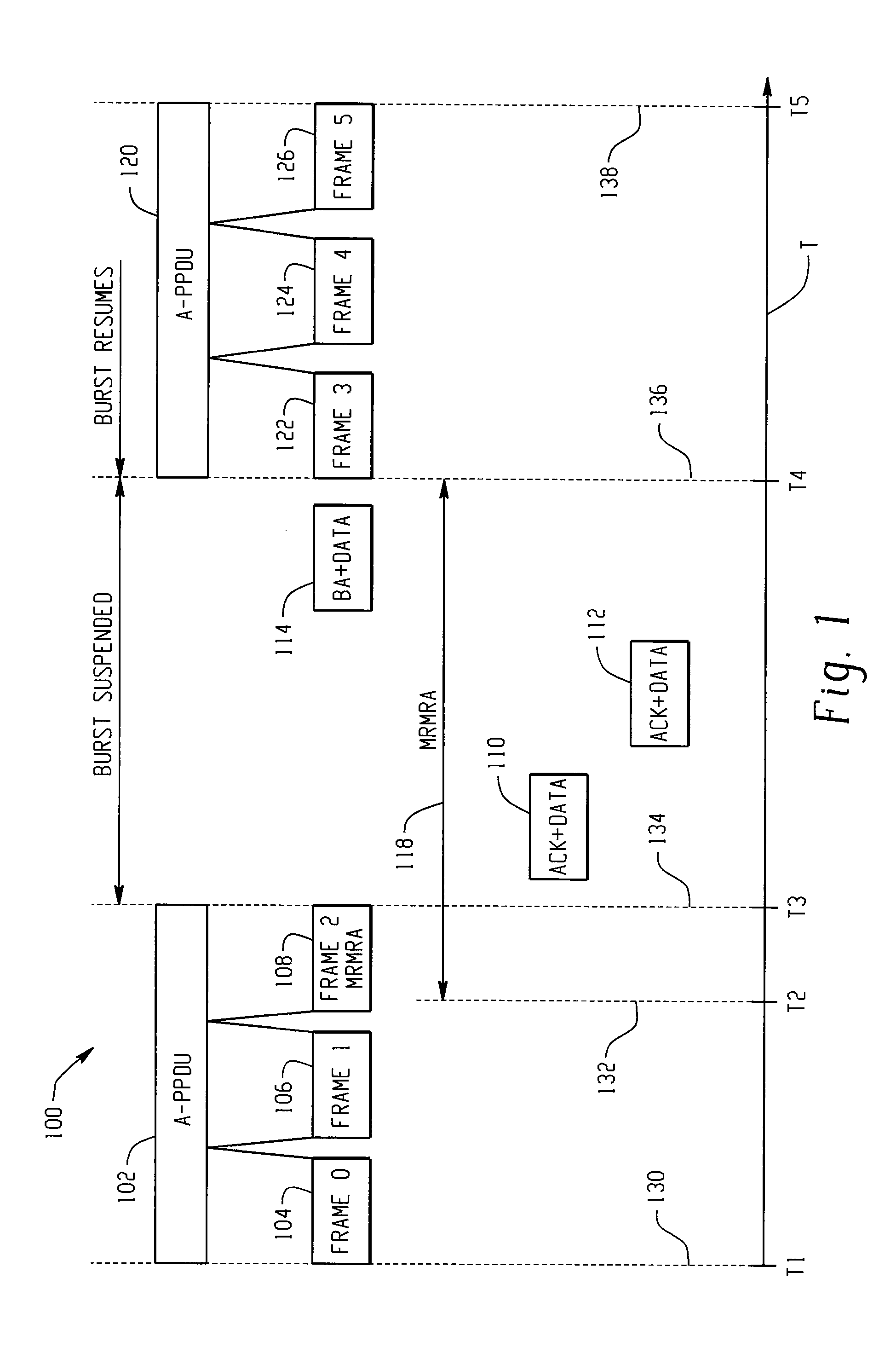
[0023]Throughout this description, the preferred embodiment and examples shown should be considered as exemplars, rather than limitations, of the present invention. The present invention is directed to a multi-rate aggregation scheme that is in the form of PSDU bursting, which aggregates multiple frames, either to the same receiver or a number of receivers of the same rate, in a single PSDU and bursts a number of PSDUs of various rates in sequence. To allow for a MRMRA, the PSDU bursting suspends temporarily after it transmits a MRMRA. After receiving acknowledgements from the recipients of the MRMRA, a block acknowledgement, is transmitted and the bursting resumes. This approach seamlessly combines MRMRA and multi-rate aggregation without introducing any degradation in channel utilization.

[0024]Referring to FIG. 1, there is illustrated an example timing diagram 100 illustrating an aspect of the present invention. A timeline T is employed for the purpose of illustrating the various ...


PUM


Abstract

A method for sending a multi-rate multi-receiver message containing a multi-receiver multi-response aggregate. The multi-rate multi-receiver aggregate is transmitted until a multi-receiver multi-response aggregate embedded within the multi-rate multi-receiver aggregate is encountered. Transmission of the multi-rate multi-receiver aggregate is suspended for a predetermined time period. After the expiration of the predetermined time period, transmission of the multi-rate multi-receiver aggregate resumes.

Description

CROSS-REFERENCE TO RELATED APPLICATIONS[0001]This application is a continuation of U.S. application Ser. No. 11 / 032,747, filed Jan. 11, 2005 now U.S. Pat. No. 7,688,855, which claims the benefit of priority of U.S. Provisional Application No. 60 / 616,306 filed Oct. 6, 2004, the contents of which are hereby incorporated by reference; and is a continuation-in-part of U.S. application Ser. No. 10 / 840,878, filed on May 7, 2004 now U.S. Pat. No. 7,463,642, which claims the benefit of priority of U.S. Provisional Application No. 60 / 560,303 filed Apr. 7, 2004, the contents of which are hereby incorporated by reference.BACKGROUND OF THE INVENTION[0002]The present invention relates generally to high throughput wireless networks and in particular to aggregation technology.[0003]The next generation of high throughput (HT) wireless networks, to be covered by the 802.11n specification that is currently being formed, specifies 100 Mbps at the MAC SAP (Media Access Control Service Access Port) of a...

Claims


Application Information

Patent Timeline
Patent Type & Authority Patents(United States)
IPC IPC(8): H04J3/16A47B96/02A47B96/06A47F5/00
CPCH04L47/41H04L47/14Y02B60/33Y02D30/50H04W8/04
Inventor QIAN, LU
Owner CISCO TECH INC
Learn More