Scalable cost function generator and method thereof

a cost function and generator technology, applied in the field of high-speed mixed signal integrated circuits, can solve the problems of mixing signal cost function generator circuits having to contend with variations, and pose significant challenges to cost function generator circuit design

Active Publication Date: 2013-04-30
SCINTERA NETWORKS
View PDF21 Cites 20 Cited by
  • Summary
  • Abstract
  • Description
  • Claims
  • Application Information

AI Technical Summary

Problems solved by technology

In addition, unlike an implementation in a digital circuit (e.g., digital signal processor, or DSP), a mixed signal cost function generator circuit has to contend with variations due to process, variation and temperature (PVT) and other non-ideal properties.
These requirements pose significant challenges to a cost function generator circuit design.

Method used


Image

  • Scalable cost function generator and method thereof
  • Scalable cost function generator and method thereof
  • Scalable cost function generator and method thereof

Examples


Embodiment Construction

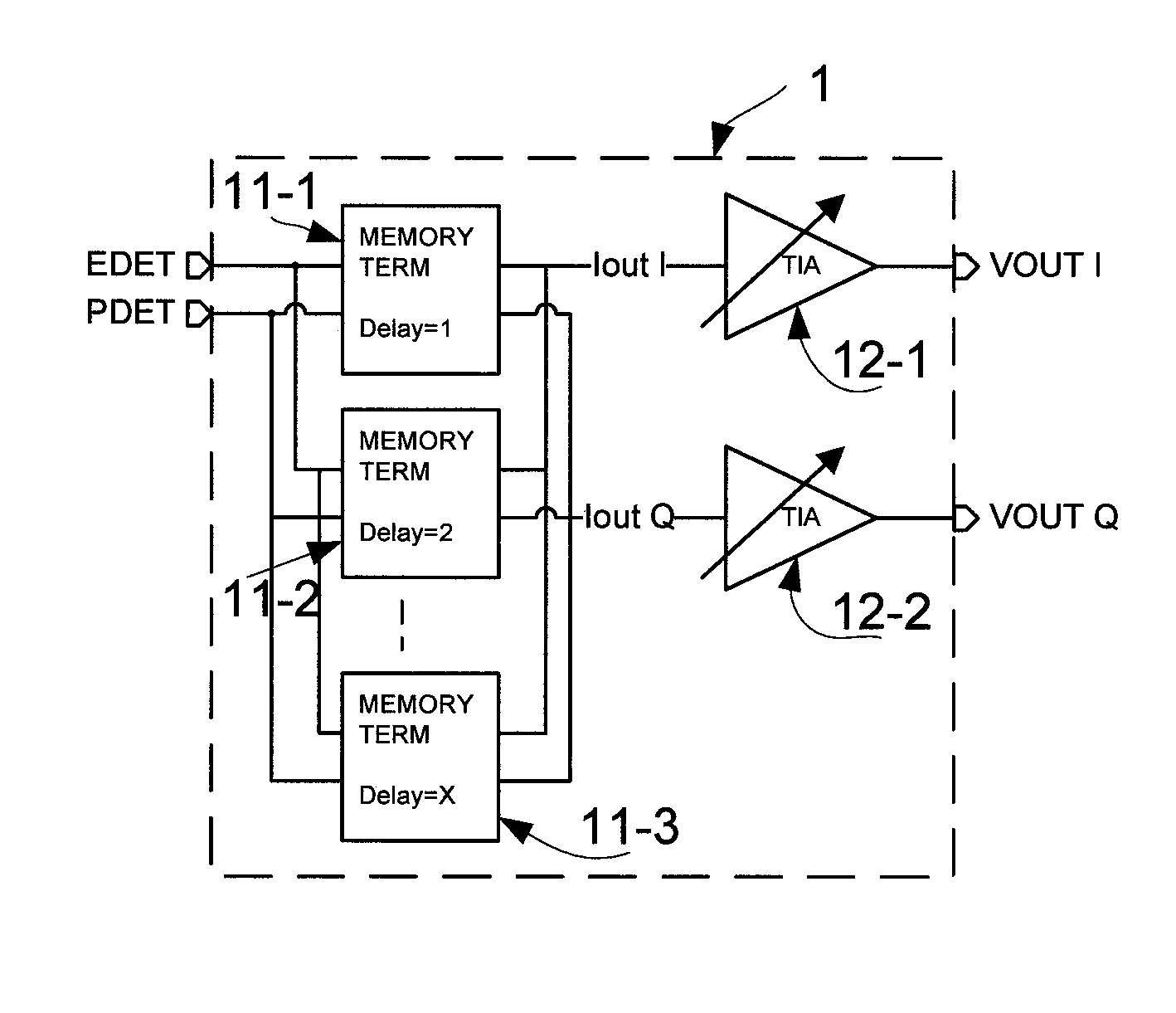
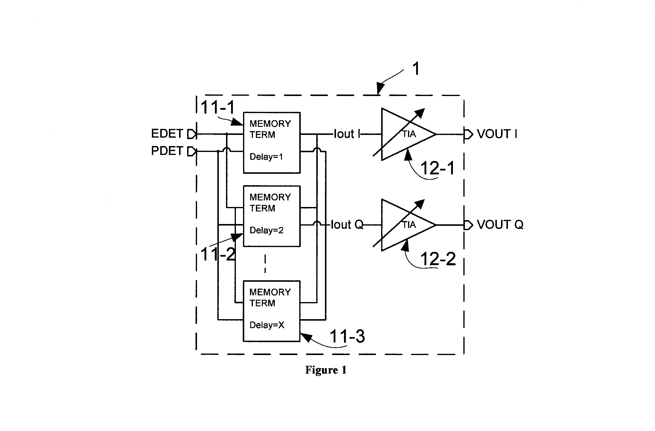
[0014]FIG. 1 shows cost function generator circuit 1, in accordance with one embodiment of the present invention. Cost function generator circuit 1 may be used, for example, in an amplitude modulation (AM) communication system. As shown in FIG. 1, cost function generator circuit 1 receives as input an envelope signal denoted by EDET and a power signal (i.e., the square of the envelope signal) denoted by PDET, and provides as output quadrature output signals VOUT I and VOUT Q. Cost function circuit 1 includes a number of memory terms 11-1 to 11-m (e.g., eleven terms), each corresponding to a different predetermined programmable delay. In FIG. 1, the predetermined programmable delays of memory terms 11-1 to 11-m may be integer multiples of a predetermined delay value (e.g., 1 nanosecond). Memory terms 11-1 to 11-m each contribute inphase and quadrature current signals that are respectively summed with the inphase and quadrature current signals of all the other memory terms to provide ...


PUM


Abstract

A cost function generator circuit includes memory terms each receiving one or more input signals, and each providing inphase and quadrature output current signals. The inphase and quadrature output currents of the memory terms are summed to provide combined inphase and quadrature output currents, respectively. Transimpedance amplifiers are provided to transform the combined inphase and quadrature output currents into an inphase output voltage and a quadrature output voltage.

Description

CROSS REFERENCE TO RELATED APPLICATIONS[0001]The present patent application is related to U.S. patent applications (the “Copending Applications”): (a) Ser. No. 12 / 037,455, entitled “High Order Harmonics Generator,” which names as inventor Frederic Roger, and was filed on Feb. 26, 2008; (b) Ser. No. 12 / 257,292, entitled “Error Signal Formation for Linearization,” which names as inventor Adric Q. Broadwell et al., and was filed on Oct. 23, 2008, now U.S. Pat. No. 8,295,394, which was issued on Oct. 23, 2012; and (c) Ser. No. 12 / 340,111, entitled “RF Squarer,” which names as inventor Frederic Roger, and was filed on the same day as the present invention, now U.S. Pat. No. 7,902,901, which was issued on Mar. 8, 2011. The Copending Applications are hereby incorporated by reference in their entireties.BACKGROUND OF THE INVENTION[0002]1. Field of the Invention[0003]The present invention relates to the high speed mixed signal integrated circuits. In particular, the present invention relates...

Claims


Application Information

Patent Timeline
Patent Type & Authority Patents(United States)
IPC IPC(8): G06G7/02
CPCH03F1/3211H03F1/3241H03F3/45183H03F2200/336H03F2201/3209
Inventor ROGER, FREDERIC
Owner SCINTERA NETWORKS
Why Eureka
Try Eureka