System and method for cooling fuel injectors

a fuel injector and cooling system technology, applied in the field of fuel injectors, can solve the problems of high operating temperature of the fuel injector, additional electrical energy required, and dimensional instability of the injector, and achieve the effects of reducing the cooling rate, reducing the flow rate, and increasing the flow ra

Active Publication Date: 2013-05-07
CATERPILLAR INC
View PDF32 Cites 7 Cited by
  • Summary
  • Abstract
  • Description
  • Claims
  • Application Information

AI Technical Summary

Benefits of technology

[0011]In one aspect, the external annular spaces for each injector are about the same size. The first or upstream fuel injector has a smaller interior annular space, which provides a lower flow rate through its interior annular space and a greater flow rate though its exterior annular space. Thus, the first or upstream injector experiences a lower cooling rate due to the smaller interior annular space. The terminal fuel injector, in contrast, includes a larger interior annular space. As a result, more fuel flows through the larger interior annular space of the terminal fuel injector for a greater cooling rate than experienced by the first or upstream injector.
[0012]In another aspect, the internal annular spaces for each injector are about the same size. The first or upstream fuel injector has a larger external annular space, which diverts flow from the interior annular space and provides a lower flow rate through its interior annular space. In other words, the first or upstream injector experiences a lower cooling rate due to the larger external annular space. The terminal fuel injector, in contrast, includes a smaller external annular space. As a result, more fuel is diverted to the internal annular space for a greater cooling rate than experienced by the first or upstream injector.
[0013]In another aspect, a total annular space for each injector are about the same size for each injector. The first or upstream fuel injector has a smaller interior annular space and larger external annular space, which provides a lower flow rate through its interior annular space and a greater flow rate through its exterior annular space. The terminal fuel injector, in contrast, includes a larger interior annular space and smaller external annular space. As a result, more fuel flows through the larger interior annular space of the terminal fuel injector for a greater cooling rate than experienced by the first or upstream injector.
[0014]An improved fuel injector is also disclosed which includes a nozzle case. One or more slots are strategically placed in the nozzle case in general alignment with the valve and solenoid assembly. Fuel from the fuel rail will pass through the strategically placed slots in the nozzle case and provide an increased flow or exposure to the valve and solenoid assembly for an increased cooling rate.

Problems solved by technology

However, any leakage of high-pressure atomized fuel tends to generate heat energy at or around the fuel injector.
However, to accomplish multiple injections or valve movements, additional electrical energy is required.
Therefore, the combination of efforts to reduce emissions and the use of fuel rails that link fuel injectors in series can result in high operating temperatures at the fuel injectors.
Excess heat can cause dimensional instability of the injectors, which, as shown in FIG. 1, are relatively complex individual devices.
In general, high operating temperatures can result in unreliable performance of electrically actuated fuel injectors.
Further, excess heat or high operating temperature can adversely affect the fuel by causing varnishing or lacquering of the fuel, which also adversely affects injector performance.
However, this indirect method often may not provide sufficient cooling at the fuel injectors.
However, these solutions can significantly increase the cost of an engine.

Method used


Image

  • System and method for cooling fuel injectors
  • System and method for cooling fuel injectors
  • System and method for cooling fuel injectors

Examples


Embodiment Construction

[0023]In general, the heat flux Q of a static fluid / solid system can be expressed as a function of the heat transfer coefficient h, the surface area A and temperature difference between the cooling fluid and the solid surface:

Q≈hAΔT

where Q is the heat flux (W); h is the heat transfer coefficient (W / (m2K)); A is the heat transfer surface area (m2); and ΔT is the difference in temperature between the solid surface and surrounding fluid area (K);

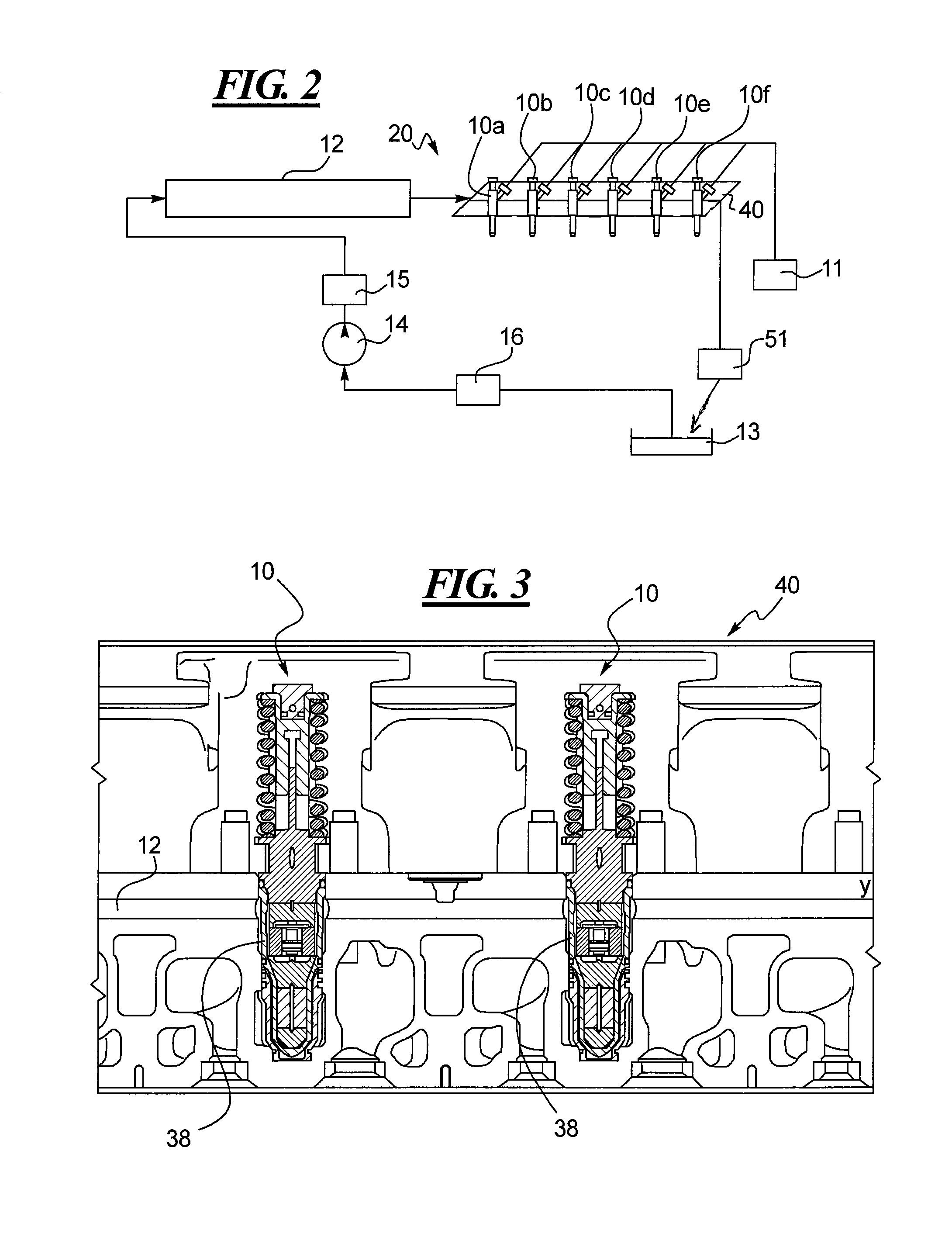
[0024]For dynamic systems, the equations used for calculating heat flux are complex and depend on the type of dynamic system. However, the heat flux of a dynamic system is also dependent upon the surface area utilized for heat transfer or the velocity of the cooling fluid or both. In this disclosure, one or both of these variables are manipulated for improving the temperature profile of fuel injectors connected in series along a fuel rail. In short, the flow area and fuel (coolant) flow rates are manipulated to increase the cooling rates of the...


PUM


Abstract

Various fuel injection systems and fuel injectors are disclosed that provide varying cooling rates for fuel injectors connected in series to fuel supply and drain rail. The local cooling rate for each injector is manipulated to balance the heat flux or heat transfer across the injectors disposed along the rail. The cooling rates may be manipulated by varying sizes of openings or slots in the nozzle case, by varying annular spaces disposed between the nozzle case and the portion of the injector body that houses the actuator and solenoid assembly, and by varying the size of annular spaces disposed between the nozzle case and the cylinder head. Strategic placement of slots in the nozzle case that direct more flow at the portion of the injector body that houses the actuator and solenoid assembly may also be employed. As a result, the operating temperatures of fuel injectors connected in series to a fuel rail can be manipulated and moderated so the downstream injectors are not prone to overheating.

Description

TECHNICAL FIELD[0001]This disclosure relates generally to fuel injectors. More specifically, this disclosure relates to a system and method for cooling fuel injectors linked in series to a low pressure fuel supply and drain rail.BACKGROUND[0002]Some low pressure fuel supply and drain rail systems for diesel engines include fuel injectors linked in series to the low pressure fuel supply and drain rail (hereinafter, the “fuel rail”). That is, fuel is delivered by the fuel rail to the first fuel injector, which passes fuel onto the next injector and so on. The fuel injectors and fuel becomes increasingly hot as the fuel passes from the first fuel injector in communication with the fuel rail to the other fuel injectors disposed downstream because heat is added to the fuel rail at each injector for a variety of reasons. For example, hot fuel spilled from a fuel injector to the surrounding injector bore in the cylinder head can generate substantial amounts of heat that is transferred back...

Claims


Application Information

Patent Timeline
Patent Type & Authority Patents(United States)
IPC IPC(8): F02M61/14F01P1/06B05B1/24B05B15/00
CPCF02M53/043F02M63/0017F02M63/007F02M57/023
Inventor COLDREN, DANA R.ROGERS, ERIC L.O'SHEA, FERGAL M.WANG, LIFENGJOSHI, MANDAR A.
Owner CATERPILLAR INC
Why Eureka
Try Eureka