Horizontally-oriented gasifier with lateral transfer system

a gasifier and horizontal transfer technology, applied in the direction of electrochemical generators, furnace types, lighting and heating apparatus, etc., can solve the problems of insufficient treatment of prior systems and processes, and less desirable disposal of waste materials by incineration

Inactive Publication Date: 2013-05-07
PLASCO ENERGY GROUP INC
View PDF229 Cites 2 Cited by
  • Summary
  • Abstract
  • Description
  • Claims
  • Application Information

AI Technical Summary

Benefits of technology

[0026]This invention provides a horizontally-oriented gasifier with lateral transfer system that enables extraction of volatiles throughout the various stages of gasification of carbonaceous feedstock to be optimized. Feedstock is introduced at one end of the gasifier and is moved through the gasifier during processing by one or more lateral transfer units. The temperature at the top of the material pile generally increases as gasification proceeds through drying, volatilization and char-to-ash conversion (carbon conversion) with the simultaneous production of CO and CO2. A control system obtains information from measurable parameters such as temperature and pile height or profile and manages the movement of each lateral transfer unit independently.

Problems solved by technology

It is becoming less desirable to dispose of waste material by incineration because of the extreme waste of fuel in the heating process and the further waste of disposing, as a residual waste, material that can be converted into a useful syngas and solid material.
The gas produced during the gasification of carbonaceous feedstock is usually very hot but may contain small amounts of unwanted compounds and requires further treatment to convert it into a useable product.
Prior systems and processes have not adequately addressed the problems that must be dealt with on a continuously changing basis.

Method used


Image

  • Horizontally-oriented gasifier with lateral transfer system
  • Horizontally-oriented gasifier with lateral transfer system
  • Horizontally-oriented gasifier with lateral transfer system

Examples


example 1

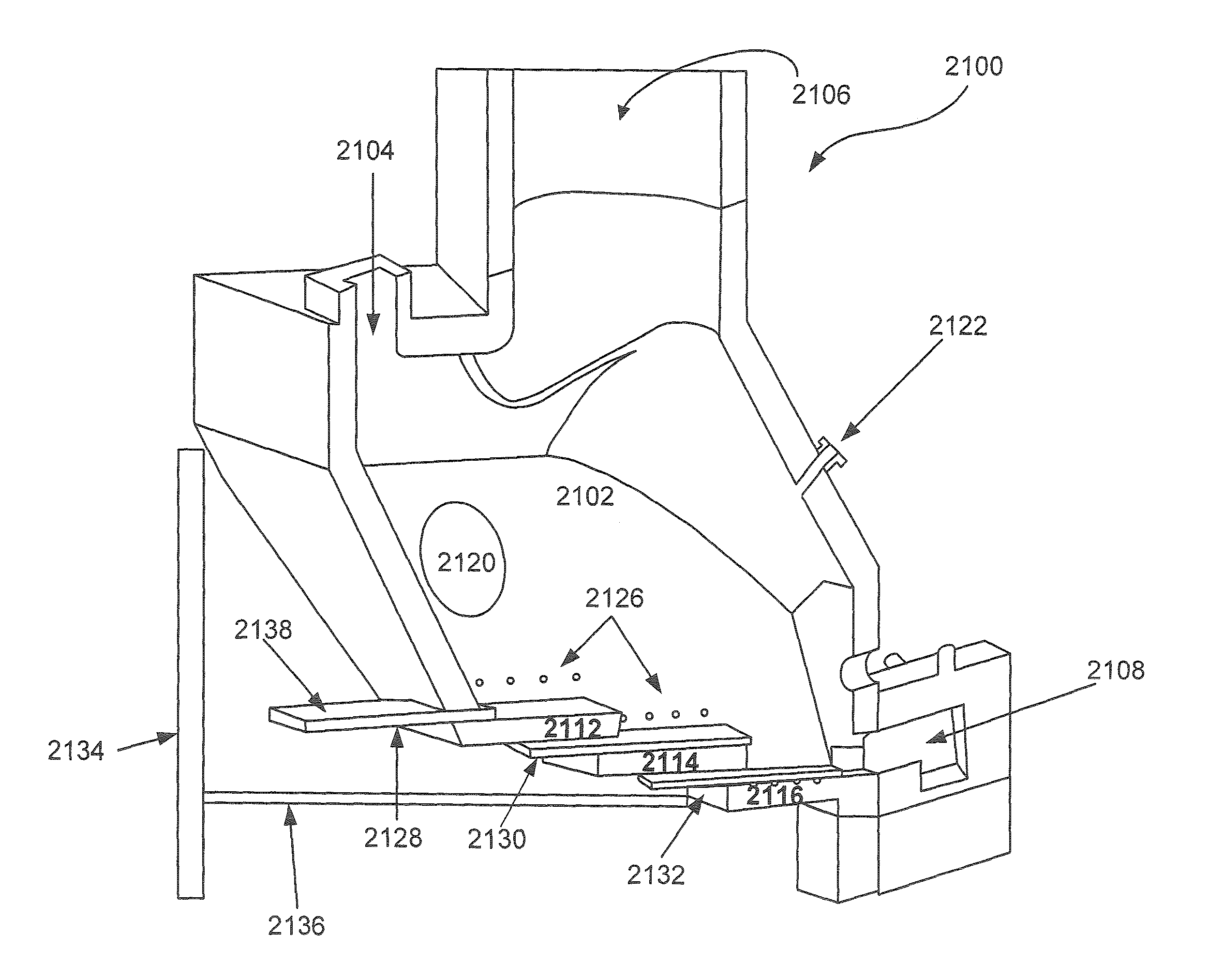
[0217]Referring to FIGS. 4 to 10, in one embodiment, the gasifier (2100) comprises a refractory-lined horizontally-oriented gasification chamber (2102) having a feedstock input (2104), gas outlet (2106), a solid residue outlet (2108), and various service (2120) and access ports (2122). The gasification chamber (2102) has a stepped floor with a plurality of floor levels (2112, 2114 and 2116). Each floor level is sloped between about 5 and about 10 degrees. Each floor level has a series of additive inputs (2126) located in the side walls proximal to the floor level to allow for the addition of oxygen and / or steam.

[0218]Movement through the steps is facilitated by the lateral transfer system. In this example, FIGS. 4 to 9, the lateral transfer system comprises a series of moving shelf units (2128, 2130, 2132) in which material is predominantly moved through the gasifier by sitting on top of the shelf with a small fraction of material being pushed by the leading edge of the shelf. As sh...

example 2

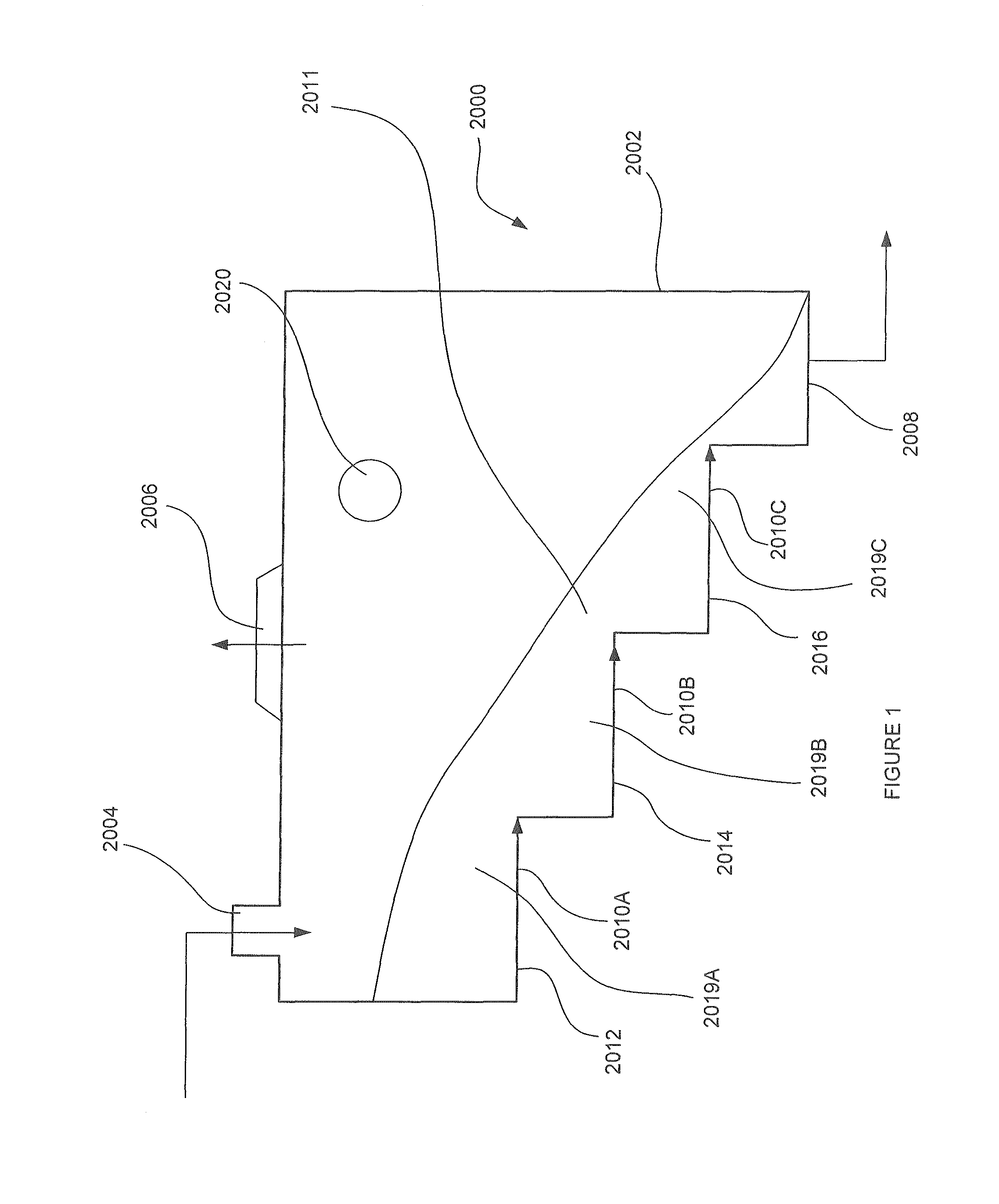
[0228]Referring to FIGS. 11 to 25, in one embodiment the gasifier (2200) comprises a refractory-lined horizontally-oriented gasification chamber (2202) having a feedstock input (2204), gas outlet (2206), a solid residue outlet (2208), and various service (2220) and access ports (2222). The gasification chamber (2202) is a refractory-lined steel weldment having a stepped floor with a plurality of floor levels (2212, 2214 and 2216).

[0229]The solid residue outlet is equipped with an ash extractor comprising an extractor screw (2209) which will pull the ash out of the gasifier and feed it into an ash conveyor system.

[0230]Referring to FIG. 16, the refractory is a multilayer design with a high density chromia layer (2402) on the inside to resist the high temperature, abrasion, erosion and corrosion, a middle, high density alumina layer with medium temperature resistance and insulation factor (2404) and an outer very low density insboard material with very high insulation factor (2406) th...

example 3

[0253]Referring to FIG. 26, in the embodiment of the invention described in Example 2 a staggered ram sequence control strategy can be implemented to facilitate movement of the rams. A summary of an exemplary ram sequence is as follows:[0254]1. Ram C (2232) move fixed distance (with adjustable setpoint), creating a pocket at the start of Step C (2216).[0255]2. Ram B (2230) follows as soon as Ram C (2232) passes a trigger distance (trigger distance has adjustable setpoint). Ram B pushes / carries material to immediately fill the pocket at the start of Step C (2216). Feedback control is to stroke as far as necessary to block level switch C (2217), or minimum setpoint distance if already blocked, or maximum setpoint distance if blocking does not occur. At the same time as Ram B (2230) is filling the pocket at the start of Step C (2216), it is creating a pocket at the start of Step B (2230).[0256]3. Ram A (2228) follows as soon as Ram B (2228) passes a trigger distance. Ram A (2228) pushe...


PUM

PropertyMeasurementUnit
temperatureaaaaaaaaaa
pressuresaaaaaaaaaa
temperatureaaaaaaaaaa

Abstract

A method and apparatus is described for the efficient conversion of carbonaceous feedstock including municipal solid waste into a product gas through gasification. More specifically, a horizontally-oriented gasifier having one or more lateral transfer system for moving material through the gasifier is provided thereby allowing for the horizontal expansion of the gasification process such that there is sequential promotion of feedstock drying, volatization and char-to-ash conversions.

Description

CROSS REFERENCE TO RELATED APPLICATIONS[0001]This application claims benefit of priority under 35 U.S.C. §119(e) from U.S. Provisional Application Ser. No. 60 / 798,439, filed May 5, 2006. This application also claims benefit of priority to International Patent Application No. PCT / CA2006 / 000881, filed Jun. 5, 2006. This application also claims benefit of priority under 35 U.S.C. §19(e) from U.S. Provisional Application Ser. No. 60 / 864,116, filed Nov. 2, 2006. This application also claims benefit of priority under 35 U.S.C. §119(e) from U.S. Provisional Application Ser. No. 60 / 911,179, filed Apr. 11, 2007. This application also claims benefit of priority under 35 U.S.C. §119(e) from U.S. Provisional Application Ser. No. 60 / 797,973, filed May 5, 2006. The contents of all of the aforementioned applications are hereby expressly incorporated by reference in their entirety and for all purposes.FIELD OF THE INVENTION[0002]This invention pertains to the field of carbonaceous feedstock gasific...

Claims


Application Information

Patent Timeline
Patent Type & Authority Patents(United States)
IPC IPC(8): C10B1/00C01B3/36C01B6/24
CPCC10J3/48C10J3/002C10B7/06C10J2200/15C10J2300/1603C10J2200/158C10J2300/0946C10J2300/0956C10J2300/0976C10J2300/1671C10J2200/154C10J2300/093C10J3/482C10J2200/09C10J2300/1693Y02E20/12F23K3/00F23G7/00
Inventor TSANGARIS, ANDREASCAMPBELL, KENNETH CRAIGCUI, MAO PEIDOBBS, GEOFFREYFEASBY, DOUGLAS MICHAELSHEN, ZHIYUAN
Owner PLASCO ENERGY GROUP INC
Why Eureka
Try Eureka