LED controller with de-flicker function and LED de-flicker circuit and method thereof
a technology of led controller and led controller, which is applied in the direction of lighting apparatus, electrical equipment, light sources, etc., can solve the problems of jittering of clock signal clk b>3/b>, error in duty ratio calculation, and change of duty ratio
- Summary
- Abstract
- Description
- Claims
- Application Information
AI Technical Summary
Benefits of technology
Problems solved by technology
Method used
Image

Examples
Embodiment Construction
[0035]The spirit of the present invention is to provide an LED controller, an LED de-flicker circuit, and an LED de-flicker method, which use hysteresis judgment to solve the LED flicker problem.
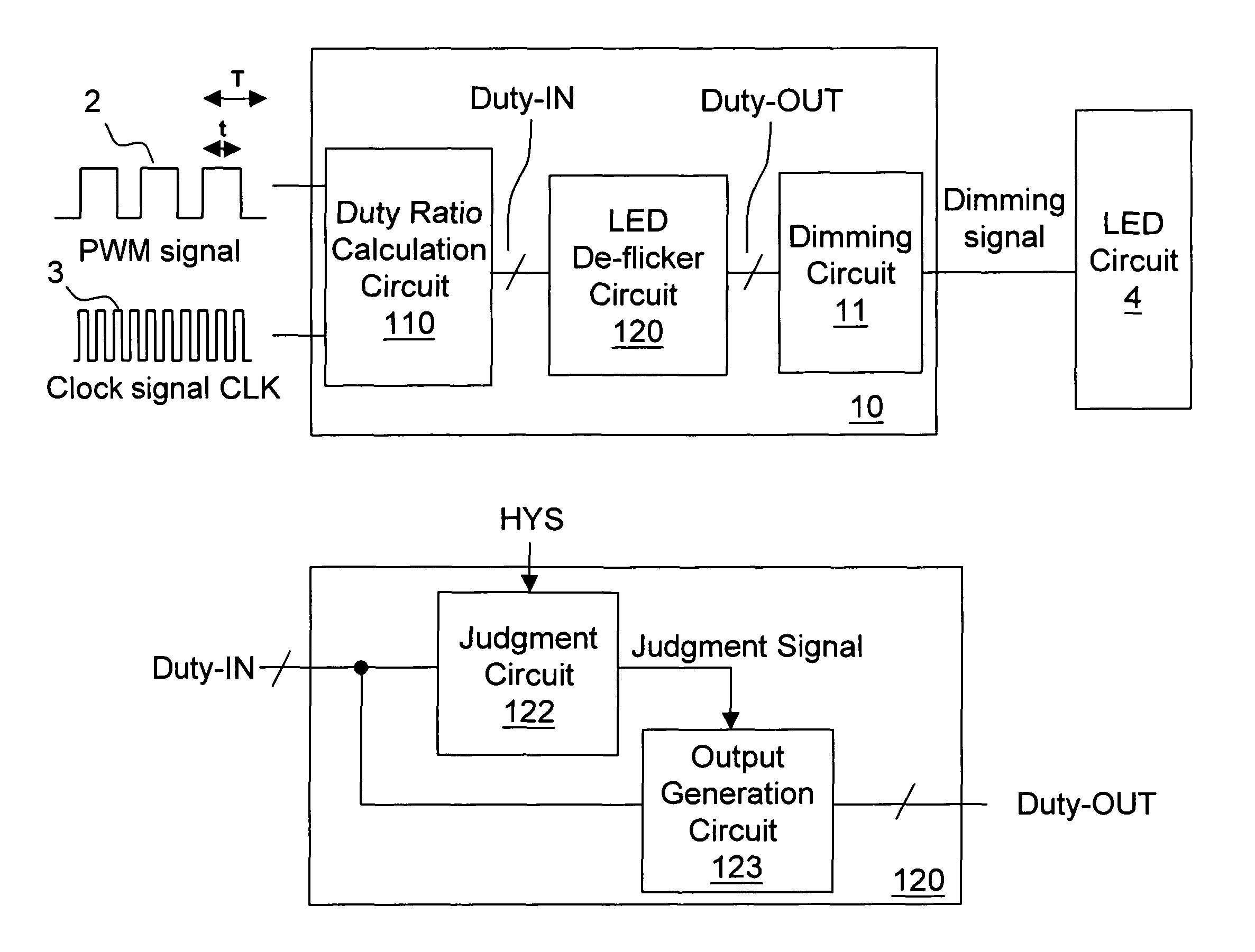
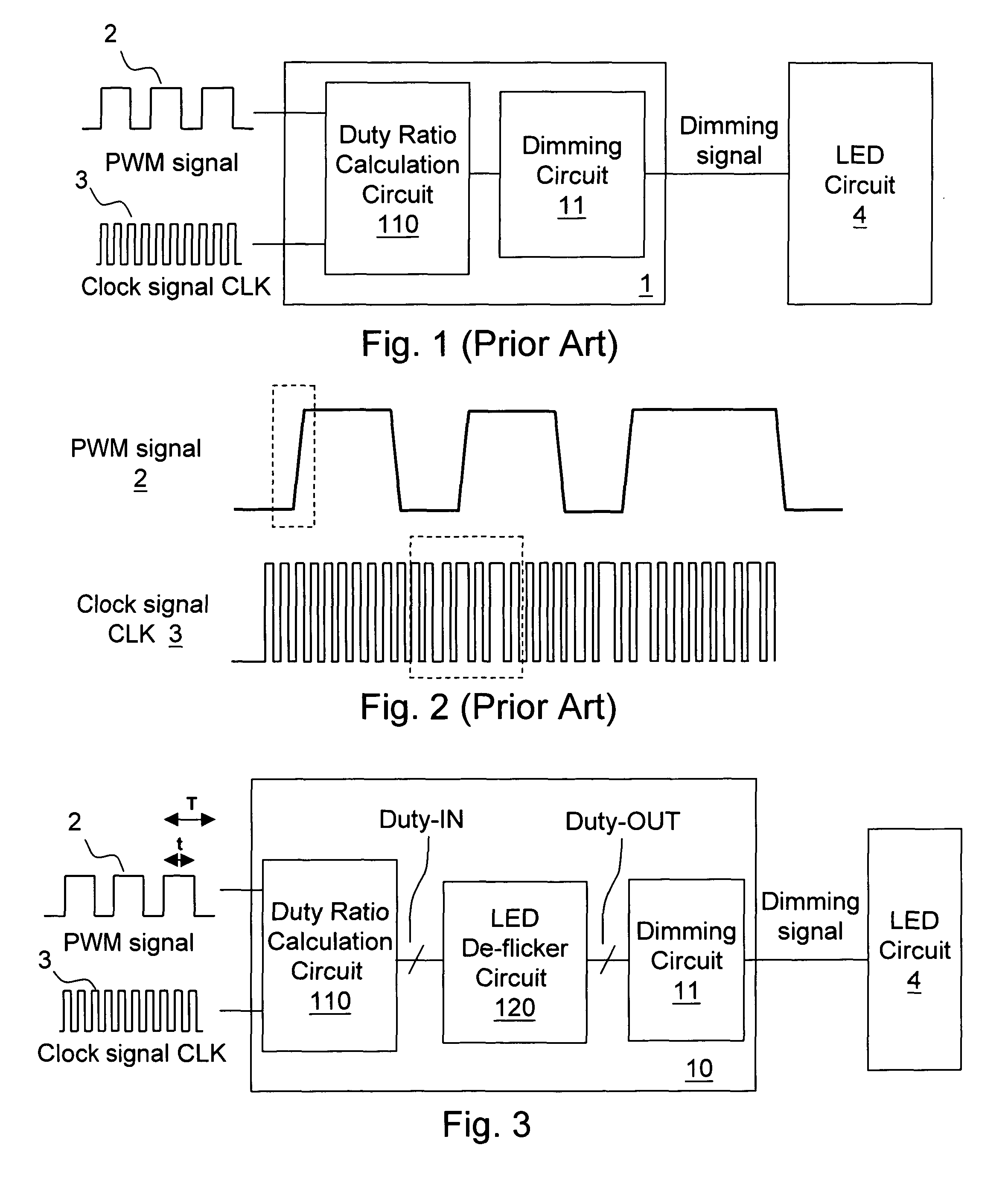
[0036]FIG. 3 shows an LED controller with de-flicker function according to an embodiment of the present invention. As shown in the figure, a PWM signal 2 is inputted to a duty ratio calculation circuit 110 in an LED controller 10. The duty ratio calculation circuit 110 calculates the duty ratio of the PWM signal 2 by the clock signal CLK 3 shown in FIG. 2 (the clock signal CLK 3 can be generated internally or provided externally), and expresses the duty ratio by an n-bit digital signal, which is the duty input signal Duty-IN. For example, if the ON time of the PWM signal 2 is t and the period is T, the duty input signal Duty-IN=(t / T)*2n.
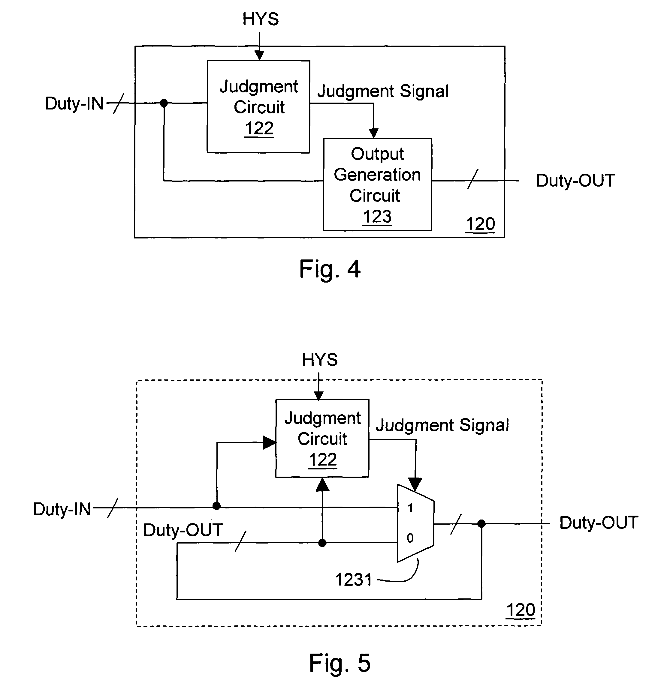
[0037]The duty input signal Duty-IN is inputted to an LED de-flicker circuit 120. The LED de-flicker circuit 120 outputs a duty output signal Duty-OUT accord...
PUM
 Abstract
Description
Claims
Application Information
 - R&D
- Intellectual Property
- Life Sciences
- Materials
- Tech Scout
- Unparalleled Data Quality
- Higher Quality Content
- 60% Fewer Hallucinations
Browse by: Latest US Patents, China's latest patents, Technical Efficacy Thesaurus, Application Domain, Technology Topic, Popular Technical Reports.
© 2025 PatSnap. All rights reserved.Legal|Privacy policy|Modern Slavery Act Transparency Statement|Sitemap|About US| Contact US: help@patsnap.com