
Method and device for recognition of paravasal bleeding

a paravasal and bleeding technology, applied in the field of paravasal bleeding recognition, can solve the problems of perivascular bleeding detection in practice, faulty vascular access, therapy interruption, etc., and achieve the effect of increasing the safety and reliability of the monitoring system

Active Publication Date: 2013-05-14
FRESENIUS MEDICAL CARE DEUTSCHLAND GMBH
View PDF11 Cites 6 Cited by
  • Summary
  • Abstract
  • Description
  • Claims
  • Application Information

AI Technical Summary

Benefits of technology

The present invention provides a method and arrangement for detecting faulty vascular access in extra-corporeal blood treatment. This method and arrangement can be combined with other methods and arrangements to increase safety and reliability. Additionally, the patent describes methods and arrangements that are disclosed in other patents. The technical effect of this invention is the improved detection of faulty vascular access, which ensures patient safety and treatment effectiveness.

Problems solved by technology

Among the possible complications is a faulty vascular access which is attributable to, for example, the needle slipping out or being drawn in.
By this means, the blood treating apparatus is changed to a state which is safe for the patient, but one which results in the therapy being interrupted.
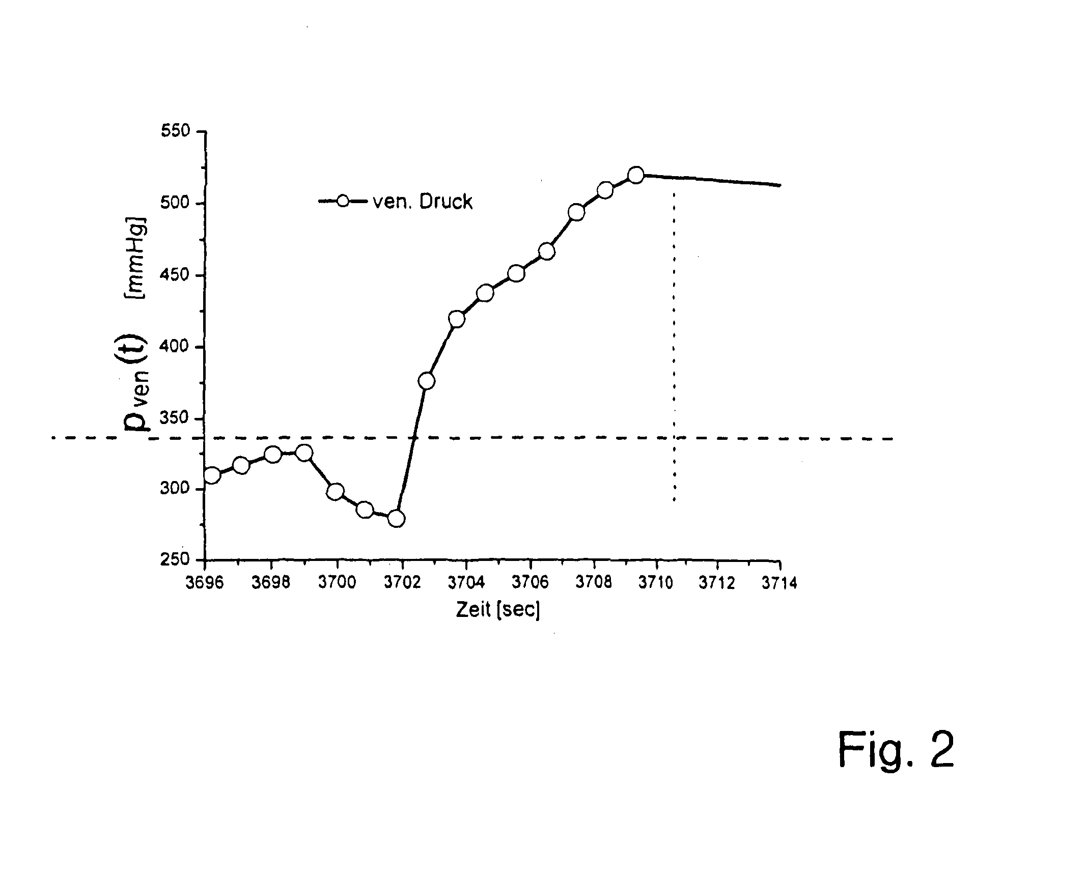
Because cases of perivascular bleeding produce only a very slow rise in pressure in the line running to the puncture needle or in the puncture needle itself, the detection of perivascular bleeding is a problem in practice.
If the pressure in the line or needle is still well below the limiting value of pressure at which the known pressure-monitoring arrangements respond, the rise in pressure per unit of time, which is only small, is not noticed at first, even though more and more blood is continuously bleeding into the tissue at the time and builds up there when this happens, as a result of which more and more harm is done to the patient.
A considerable amount of time therefore passes, in which blood bleeds into the tissue undetected, until the limiting level of pressure is reached.

Method used


Image

  • Method and device for recognition of paravasal bleeding
  • Method and device for recognition of paravasal bleeding
  • Method and device for recognition of paravasal bleeding

Examples


Embodiment Construction

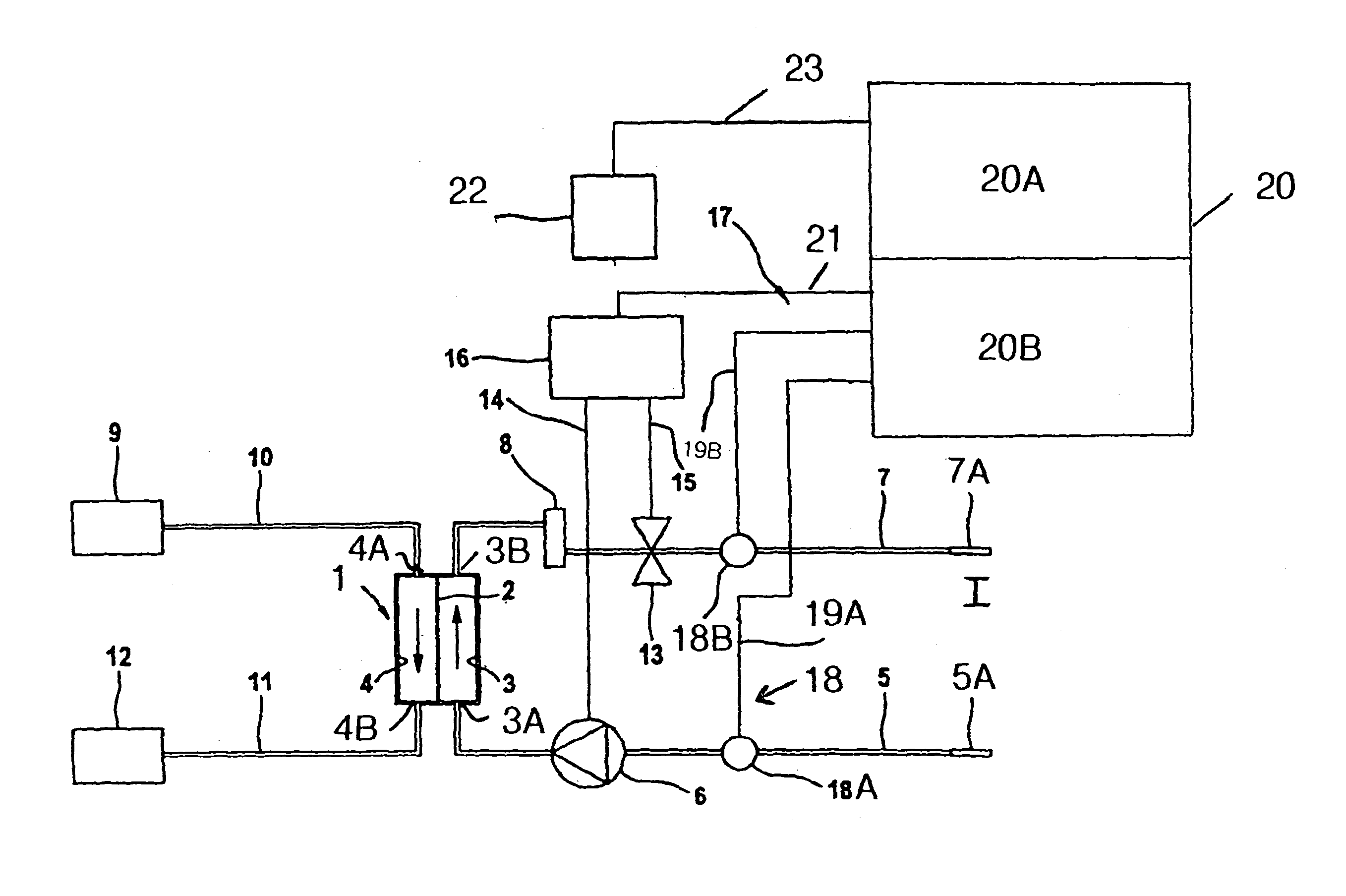
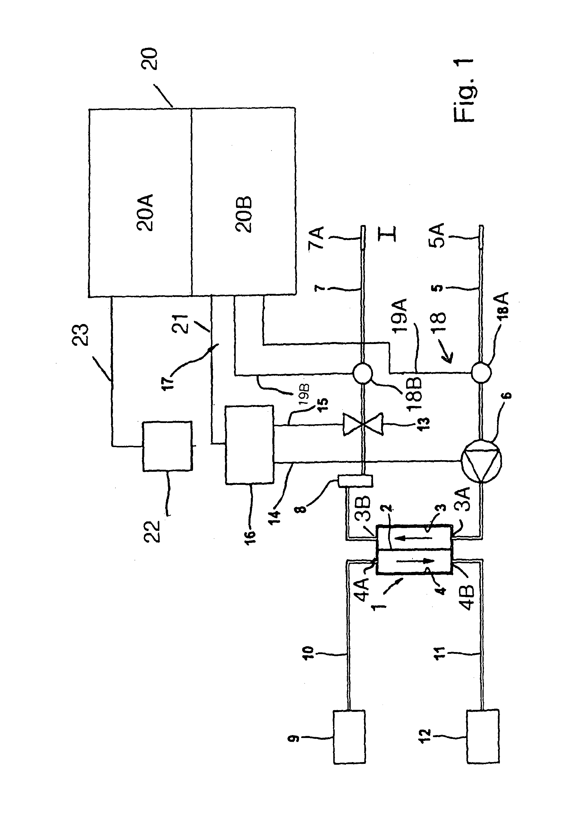
[0027]FIG. 1 is a highly simplified schematic view of a dialysis apparatus as an embodiment of extra-corporeal blood treating apparatus.

[0028]The dialysis apparatus has, as a blood treating means, a dialyzer 1 which is divided by a semi-permeable membrane 2 into a blood chamber 3 and a dialysis-fluid chamber 4. Connected to the inlet 3A of the blood chamber 3 is an arterial blood line 5 into which a peristaltic blood pump 6 is connected. From the outlet 3B of the blood chamber 3, a venous blood line 7 runs to the patient. Connected into the venous blood line 7 is a drip chamber 8. Connected to the ends of the arterial and venous blood lines 5, 7 are needles 5A and 7A which are respectively inserted in appropriate arterial and venous blood vessels (shunts) of the patient. The arterial and venous blood lines 5, 7 form the arterial and venous segments, respectively, of the extra-corporeal blood circuit I. The blood lines are part of a system of flexible tubing which is designed to be d...


PUM


Abstract

A method and a device for recognition of paravasal bleeding upon a supplying of blood to a vascular access via a line and / or upon the removal of blood from a vascular access via a line is provided. A device for extracorporeal blood treatment comprising a device for recognition of paravasal bleeding is also provided. The method and the device are based on the change of arterial pressure in the arterial branch or the venous pressure in the venous branch of the extra-corporeal circuit being registered during the extracorporeal blood treatment. One aspect of the method and the device is that pressure changes that come from a pressure level exhibiting a large difference from a reference value are more strongly considered than those that come from a pressure level that exhibits only a minor difference from the reference value.

Description

CROSS REFERENCE TO RELATED APPLICATIONS[0001]This is a 371 national phase application of PCT / EP2009 / 008128 filed Nov. 14, 2009, which claims priority from German Patent Application No. DE 10 2008 057 994.7, filed Nov. 19, 2008.FIELD OF THE INVENTION[0002]The present invention relates to a method and arrangement for detecting perivascular bleeding when blood is being fed to a vascular access via a line and / or when blood is being taken from a vascular access via a line, and in particular perivascular bleeding during extra-corporeal blood treatment, such for example as for the purposes of hemodialysis, hemofiltration or hemodiafiltration. As well as this, the present invention also relates to an apparatus for extra-corporeal blood treatment, in particular for the purposes of hemodialysis, hemofiltration or hemodiafiltration, which has an arrangement for detecting perivascular bleeding.BACKGROUND[0003]Arrangements for feeding blood to a vascular access and / or for taking blood from a vas...

Claims


Application Information

Patent Timeline
Patent Type & Authority Patents(United States)
IPC IPC(8): A61M37/00A61B5/02
CPCA61M1/3653A61M1/3656A61B5/02042A61M1/3639A61M2205/3331A61M2205/18A61M1/3661A61M1/3659
Inventor KOPPERSCHMIDT, PASCALGROSS, MALTESPICKERMANN, REINER
Owner FRESENIUS MEDICAL CARE DEUTSCHLAND GMBH
Learn More