
Microdevice for treating liquid samples

a micro-device and liquid sample technology, applied in flow mixers, electrolysis, diaphragms, etc., can solve the problems of microsystem integration chromatography uncertainty, micro-system integrating chromatography, and the delicate application of miniaturization electrophoresis, so as to reduce the source of physicochemical contamination.

Active Publication Date: 2013-05-21
COMMISSARIAT A LENERGIE ATOMIQUE ET AUX ENERGIES ALTERNATIVES +1
View PDF11 Cites 61 Cited by
  • Summary
  • Abstract
  • Description
  • Claims
  • Application Information

AI Technical Summary

Benefits of technology

This patent describes a new invention that allows for the movement of liquids using microdevices. The invention uses a fluid interface to create a tangential movement without the need for physical walls, resulting in faster flow rates and less contamination. The detachment technique used also allows for the selection of specific constituents after concentration. Overall, the invention is simpler to use, has higher flow rates, and avoids contamination.

Problems solved by technology

Indeed, all these elements contribute to parietal physicochemical contaminations as well as to intrinsically slow capillary flows in spite of the strong power applied in the pumping (significant pressure losses).
This analysis technique is indeed one of the most sensitive but its miniaturization proves to be very delicate to apply in particular because of the porous medium which is applied; there lies its main drawback.
The making of a microsystem integrating chromatography is uncertain and upstream preparation of the liquid sample remains pending.
But miniaturization of electrophoresis remains delicate since the medium allowing migration of the constituents to be analyzed is a very viscous gel.
The insertion and then the handling of a gel in an analysis chain of the lab-on-chip type are difficult to apply.
The problem is posed of being able to optimize this phenomenon by means of a configuration of suitable electrodes and of applying this phenomenon for different applications on the other hand.

Method used


Image

  • Microdevice for treating liquid samples
  • Microdevice for treating liquid samples
  • Microdevice for treating liquid samples

Examples


Embodiment Construction

[0089]In the following discussion, all potential species which are the object of the present invention (macromolecules, organelles, actinides, colloids or solid particles) will be designated by the generic term of constituents.

[0090]The invention may notably apply cross-linked liquid inclusions, the size of which may for example vary between 10 microns and one centimeter.

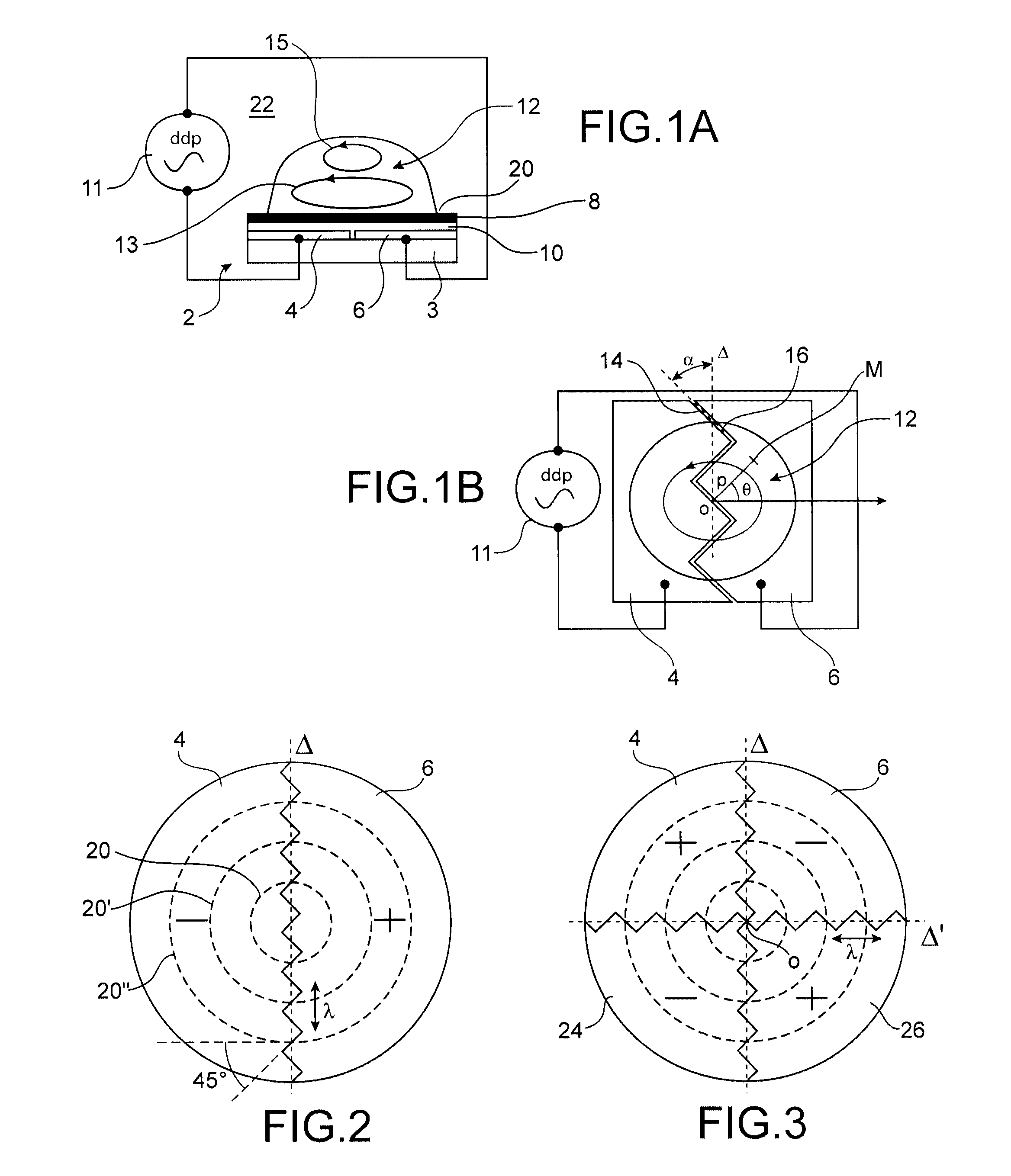
[0091]According to the invention, a liquid inclusion 12 is in a static position, placed symmetrically overlapping two electrodes 4, 6 (or more; in an even or odd number), which may be set to different electric DC or AC potentials (FIGS. 1A, 1B). These for example are electric potentials of the same absolute value but of opposite signs. These electrodes rest on a substrate 3.

[0092]In order to be compatible with electrowetting displacement technology (EWOD technology), the drop may be separated from the electrodes by an insulating layer 10 and possibly by a hydrophobic layer 8. But the device may also operate accordin...


PUM

PropertyMeasurementUnit
angleaaaaaaaaaa
angleaaaaaaaaaa
frequencyaaaaaaaaaa

Abstract

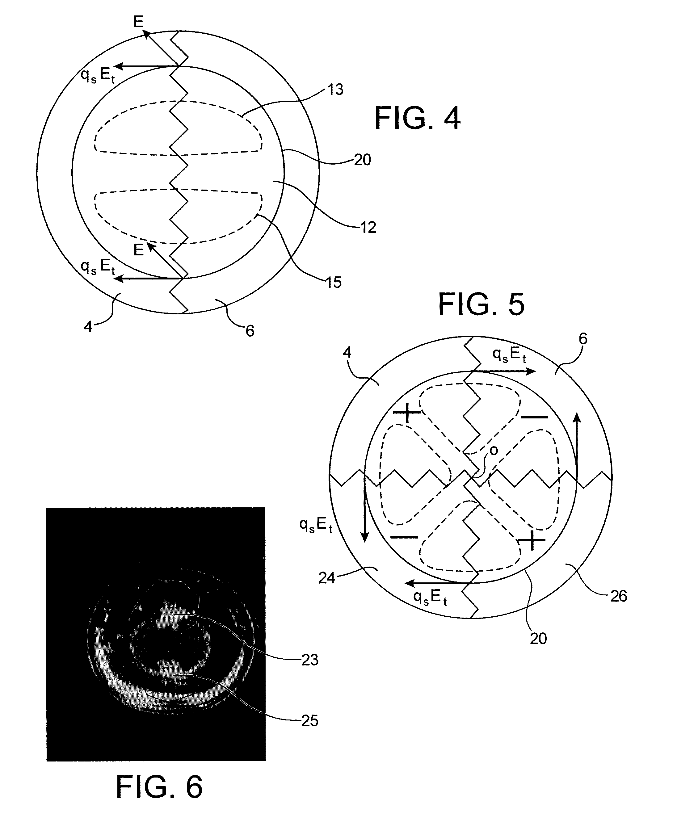
A device for forming at least one circulating flow, or vortex, at the surface of a drop of liquid, including at least two first electrodes forming a plane and having edges facing each other, such that the contact line of a drop, deposited on the device and fixed relatively to the device, has a tangent forming, when projected onto the plane of the electrodes, an angle between 0° and 90° with the edges facing each other of the electrodes.

Description

TECHNICAL FIELD AND PRIOR ART[0001]The invention relates to the field of treatment of liquid samples, in particular by centrifugation or mixing of a liquid drop.[0002]It notably applies to the preparation or to the purification of biological and chemical samples, to the fields of biomedical diagnosis, molecular biology, reprocessing of effluents, possibly radioactive effluents (extraction of actinides), and more generally to all scientific, technological and industrial fields which involve the selective extraction of macromolecules, organelles, actinides, colloids, or solid particles from a liquid sample appearing as a drop or a pool (liquid inclusions).[0003]The proposed invention also relates to the field of discrete microfluidics, preferentially used instead of continuous microfluidics (in channels) from the moment when one gets rid of pumps, valves, walls required for confining the flow, etc.[0004]Indeed, all these elements contribute to parietal physicochemical contaminations a...

Claims


Application Information

Patent Timeline
Patent Type & Authority Patents(United States)
IPC IPC(8): G01N27/26B01F5/10B01F3/08
CPCB01F3/0807B01F13/0071B01F13/0076B01L3/5088F04B19/006B01L3/5027B01L3/5085B01L2200/0647B01L2400/0415B01F23/41B01F33/3021B01F33/3031
Inventor FOUILLET, YVESDAVOUST, LAURENT
Owner COMMISSARIAT A LENERGIE ATOMIQUE ET AUX ENERGIES ALTERNATIVES
Learn More