
Compact fixed-source array test station for calibration of a semi-active laser (SAL) seeker

a semi-active laser and array test station technology, applied in direction controllers, liquid/fluent solid measurements, instruments, etc., can solve the problems of reducing affecting the accuracy of the test station, so as to reduce the distance between sources and reduce the overall scale of the test station. , the effect of reducing the distance between sources

Active Publication Date: 2013-05-21
RAYTHEON CO
View PDF3 Cites 4 Cited by
  • Summary
  • Abstract
  • Description
  • Claims
  • Application Information

AI Technical Summary

Benefits of technology

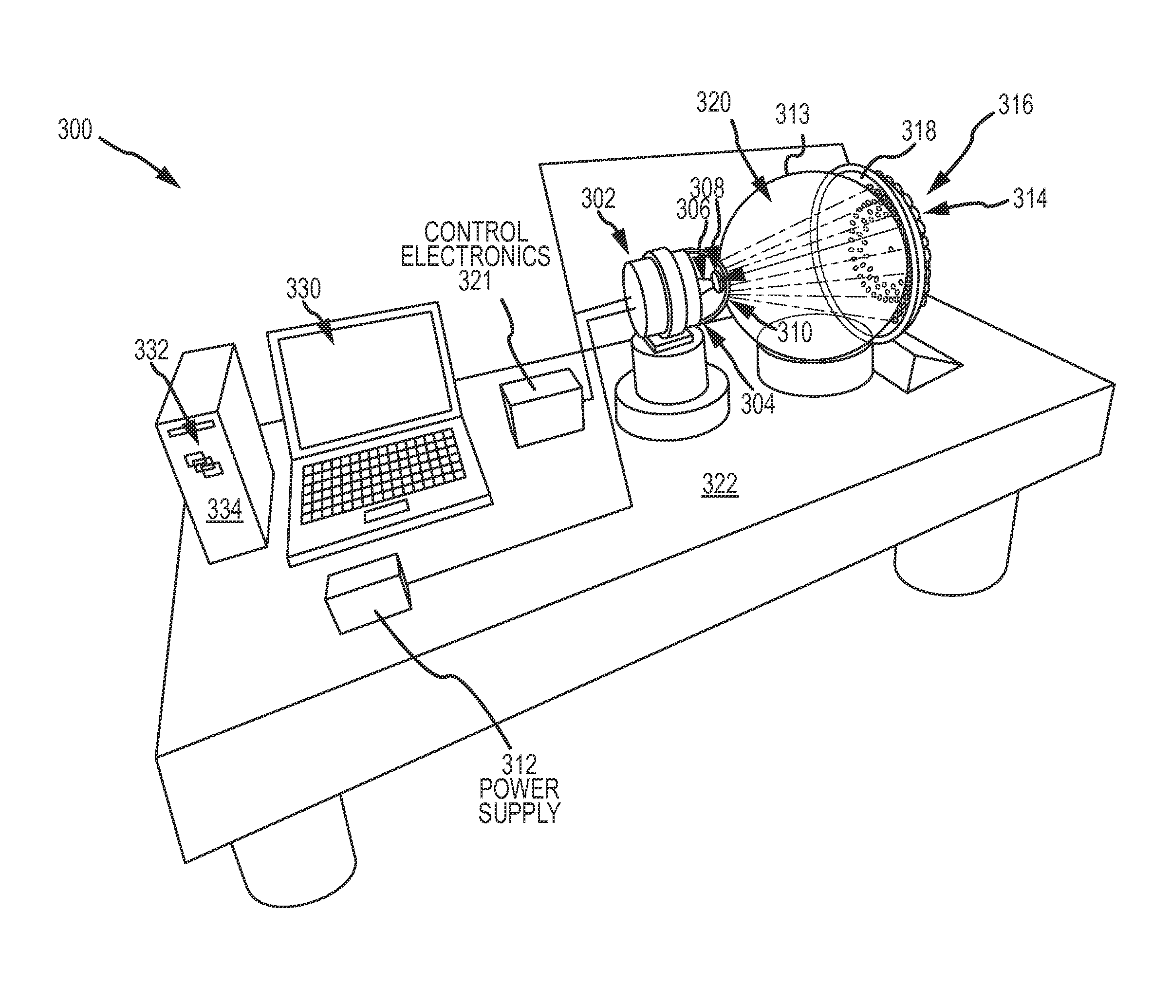
[0016]An array of fixed optical sources generates respective temporally pulsed divergent optical beams. A spherical lens having a first side is positioned at a location in front of where the entrance pupil of the seeker would be located. The spherical lens comprises one or more materials each having an index of refraction greater than one and less than or equal to two. The sources are positioned on a surface of a focal sphere at the effective focal length of the spherical lens offset from a second, opposite side of the spherical lens over the entire FOV of the seeker and aligned along respective radial lines to the center of the spherical lens. The spherical lens collimates each divergent optical beam to form a collimated optical beam that overlaps the entire entrance pupil of the seeker. The spherical lens reduces the overall scale of the test station, reducing both the distance from the sources to the entrance pupil of the seeker and reducing the distance between sources to cover the FOV.

Problems solved by technology

This test station and methodology is both expensive and slow.
Currently, the total cost of a test station is a few to several hundred thousand dollars for the Q-switched laser and focusing optics, the collimator and the 3-axis stage.
The cost is driven by the required angular resolution of both the source and rotation of the stage.
In a manufacturing environment that must calibrate thousands of seekers the time requirement is burdensome and expensive.

Method used


Image

  • Compact fixed-source array test station for calibration of a semi-active laser (SAL) seeker
  • Compact fixed-source array test station for calibration of a semi-active laser (SAL) seeker
  • Compact fixed-source array test station for calibration of a semi-active laser (SAL) seeker

Examples


Embodiment Construction

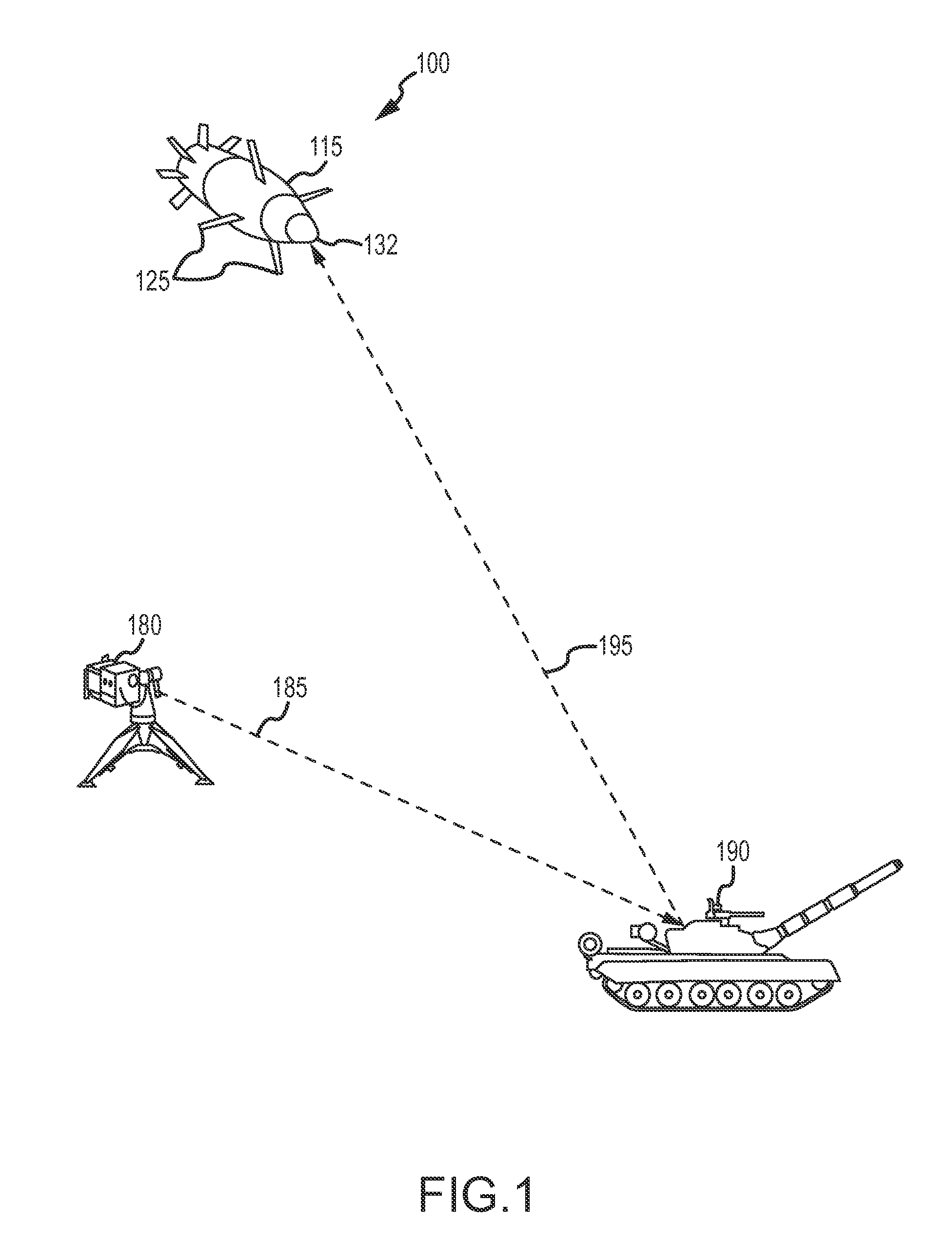
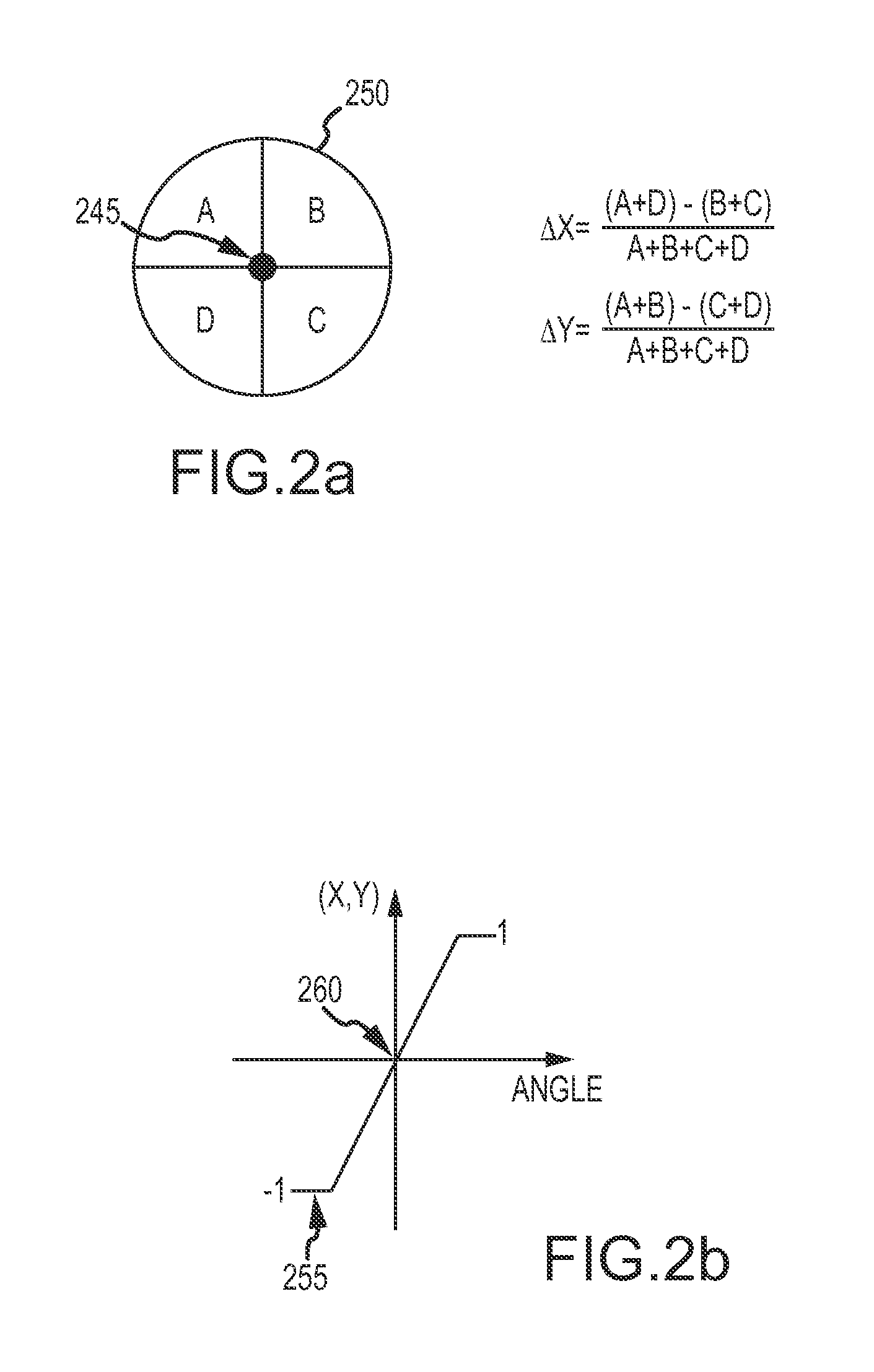
[0030]The present invention provides a compact cost-effective high-throughput test station for testing optical sensors that require stimulus at fixed angular positions over a FOV. For example, SAL seekers require stimulus one point at a time over the FOV to perform the STF calibration to generate the transfer function. The station may also be used to perform verification of the transfer function, characterization of seeker performance in response to a video signal stimulus and to calibrate the boresight alignment between the SAL and infrared (IR) sensors in a dual-mode system. A dual-mode sensor system typically consists of co-aligned SAL and long wave infrared (LWIR) sensors, but in general the IR imaging sensor can operate in any desired band. The system may also be used to calibrate the distortion in an IR imaging system and to calibrate the gimbal orientation in a gimbaled system. These tests may require source activation profiles with temporal and / or spatial patterns. The diffe...


PUM


Abstract

A fixed-source array test station provides a compact cost-effective high-throughput test bed for testing optical sensors that require stimulus at fixed angular positions. An array of fixed collimated sources at different angular positions in the sensor's FOV are positioned on a surface of a focal sphere at the effective focal length of a spherical lens and aligned along respective radial lines to the center of the spherical lens so that each said divergent optical beam is collimated by the spherical lens to form a collimated optical beam that overlaps the entire entrance pupil of the optical seeker. The sources are activated in accordance with an activation profile in order to calibrate or otherwise test the sensor.

Description

CROSS-REFERENCE TO RELATED APPLICATIONS[0001]This application claims benefit of priority under 35 U.S.C. 120 as a continuation-in-part application of co-pending U.S. patent application Ser. No. 12 / 947,234 entitled “Fixed-Source Array Test Station for Calibration of a Semi-Active Laser (SAL) Seeker” filed on Nov. 16, 2010, the entire contents of which are incorporated by reference.BACKGROUND OF THE INVENTION[0002]1. Field of the Invention[0003]This invention relates to guided projectiles that engage targets by detecting and following laser light scattered from the targets, and more particularly to a test station for calibration of the spatial transfer function (STF) of the semi-active laser (SAL) seeker and other testing, as well as testing other electro-optic (EO) sensors.[0004]2. Description of the Related Art[0005]Laser guided ordinance is commonly used to engage point targets with a high probability of success and minimal collateral damage. Such ordinance includes guided artiller...

Claims


Application Information

Patent Timeline
Patent Type & Authority Patents(United States)
IPC IPC(8): G01C19/00
CPCG06F17/00F41G7/002F41G7/226F41G7/2293G01S3/7803
Inventor BURKLAND, MICHAEL K.
Owner RAYTHEON CO
Learn More