Cable header connector

Active Publication Date: 2013-05-28
TYCO ELECTRONICS LOGISTICS AG (CH)
View PDF33 Cites 80 Cited by
  • Summary
  • Abstract
  • Description
  • Claims
  • Application Information

AI Technical Summary

Benefits of technology

[0007]A need remains for an electrical system having improved shielding to meet particular performance demands.
[0008]In one embodiment, a cable header connector is provided having a contact module having a support body and a plurality of cable assemblies held by the support body and arranged in a column. The cable assemblies include a contact sub-assembly configured to be terminated to a cable, and a ground shield coupled to and providing electrical shielding for the contact sub-assembly. The contact sub-assembly has a pair of signal contacts extending between mating ends and terminating ends. The signal contacts are terminated to corresponding signal wires of the cable at the terminating ends. A ground bridge is coupled to the support body and is electrically conductive. The ground bridge includes intercolumn bridges arranged between corresponding cable assemblies. The intercolumn bridges engage and are electrically connected to the ground shields of corresponding cable assemblies on both sides of the intercolumn bridges. The ground bridge electrically connects corresponding cable assemblies engaged by the intercolumn bridges.
[0009]In another embodiment, a cable header connector

Problems solved by technology

Signal loss and/or signal degradation is a problem in known electrical systems.
Moreover, as speed and performance demands increase, known electrical connectors are proving to be insufficient.
Such increase in density and/or reduction in size causes further strains on performance.
However, the shielding utilized in known systems is not without disadvantages.
For instance, at the interface between the signal conductors and the cables signal degradation is problematic due to improper shielding at such interface.
The termination of the cable to the signal conductors is a time consuming and complicated process.
In some systems, the cables include drain wires, which are difficult and time consuming to terminate within the connector due to their relatively small size and location in the cable.
For example, the drain wires are soldered to a grounded component of the electrical connector, which is time consum

Method used


Image

  • Cable header connector
  • Cable header connector
  • Cable header connector

Examples


Embodiment Construction

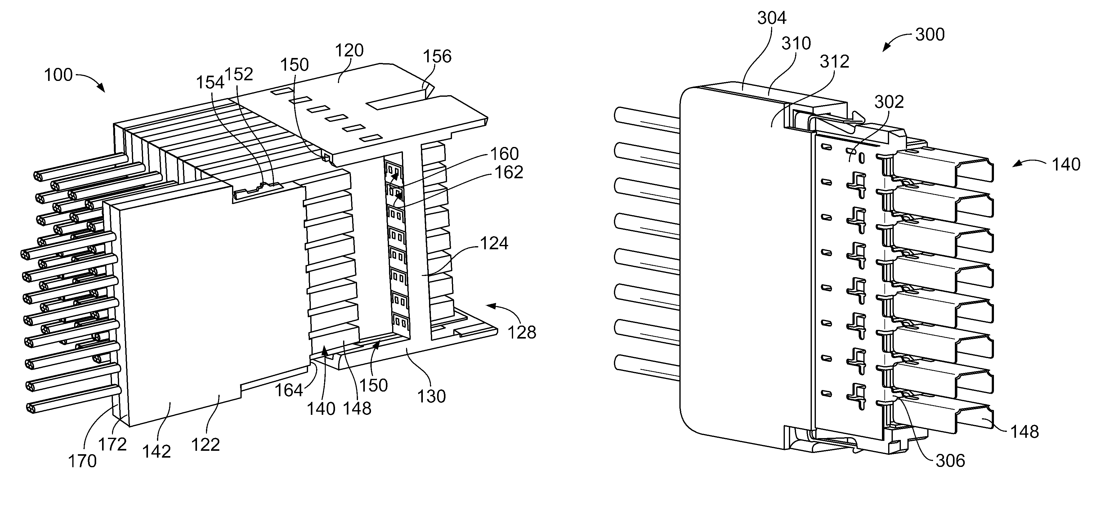
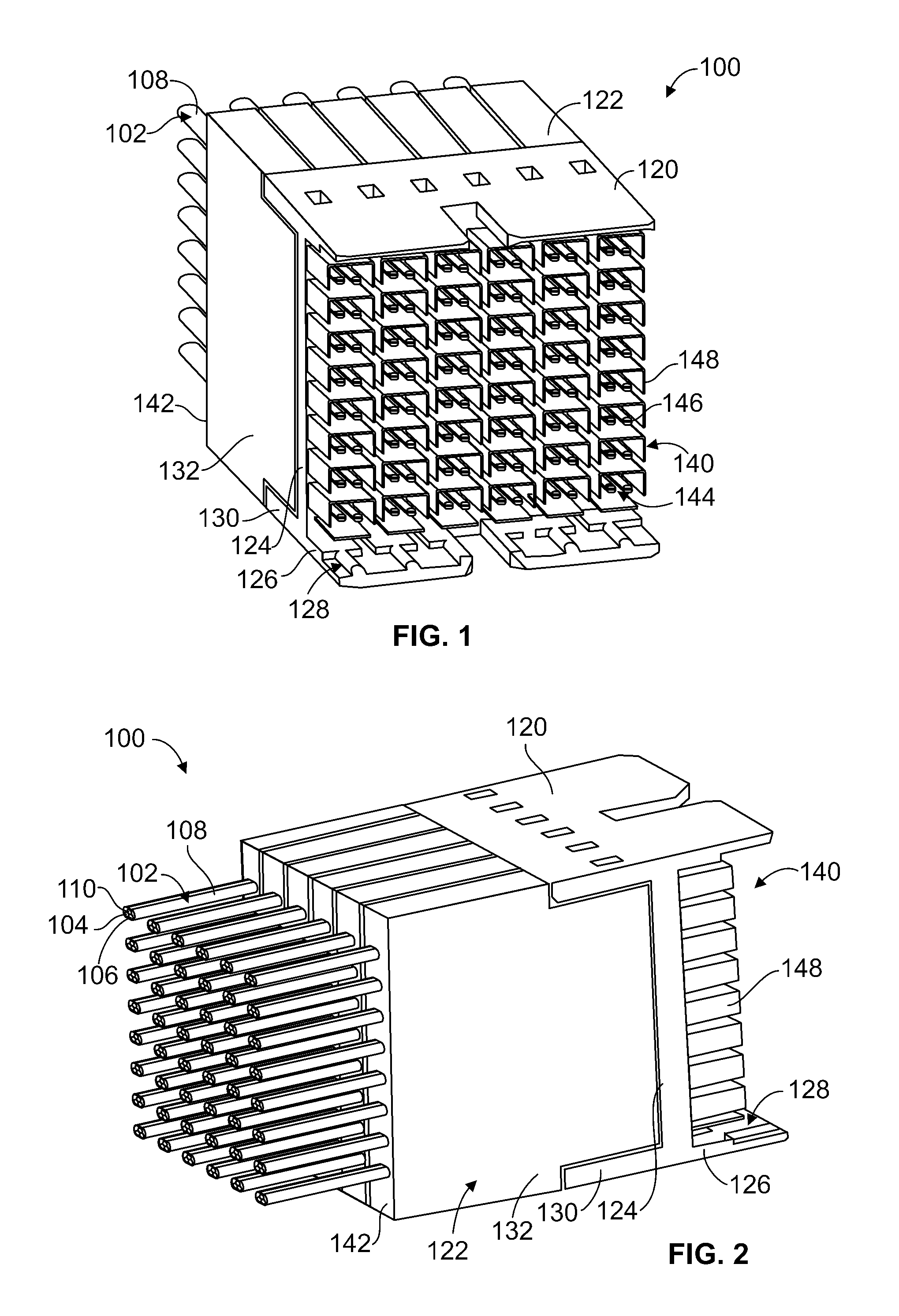
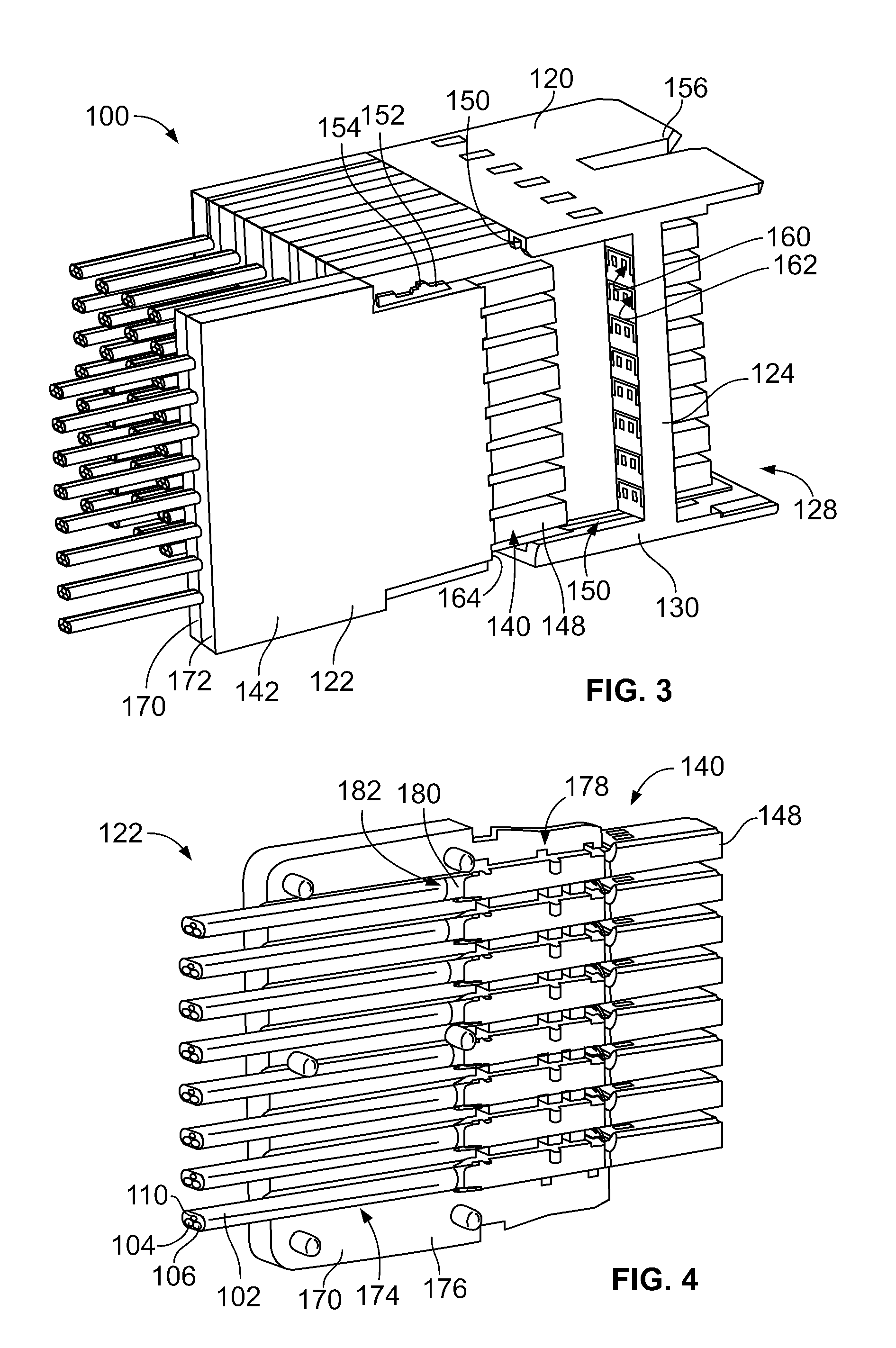
[0026]FIG. 1 is a front perspective view of a cable header connector 100 formed in accordance with an exemplary embodiment. FIG. 2 is a rear perspective of the cable header connector 100. The cable header connector 100 is configured to be mated with a receptacle connector (not shown). The receptacle connector may be board mounted to a printed circuit board or terminated to one or more cables, for example. The cable header connector 100 is a high speed differential pair cable connector that includes a plurality of differential pairs of conductors mated at a common mating interface. The differential conductors are shielded along the signal paths thereof to reduce noise, crosstalk and other interference along the signal paths of the differential pairs.

[0027]A plurality of cables 102 extend rearward of the cable header connector 100. In an exemplary embodiment, the cables 102 are twin axial cables having two signal wires 104, 106 within a common jacket 108 of the cable 102. In an exempl...


PUM


Abstract

A cable header connector includes a contact module having a support body and a plurality of cable assemblies held by the support body and arranged in a column. The cable assemblies include a contact sub-assembly configured to be terminated to a cable, and a ground shield coupled to and providing electrical shielding for the contact sub-assembly. The contact sub-assembly has a pair of signal contacts extending between mating ends and terminating ends. The signal contacts are terminated to corresponding signal wires of the cable at the terminating ends. A ground bridge is coupled to the support body and is electrically conductive. The ground bridge includes intercolumn bridges arranged between corresponding cable assemblies. The intercolumn bridges engage and are electrically connected to the ground shields of corresponding cable assemblies on both sides of the intercolumn bridges. The ground bridge electrically connects corresponding cable assemblies engaged by the intercolumn bridges.

Description

CROSS REFERENCE TO RELATED APPLICATIONS[0001]This application relates to U.S. patent application Ser. No. 13 / 314,380 filed Dec. 8, 2011, to U.S. patent application Ser. No. 13 / 314,415 filed Dec. 8, 2011, and to U.S. patent application Ser. No. 13 / 314,458 filed Dec. 8, 2011, the subject matter of each of which is herein incorporated by reference in its entirety.BACKGROUND OF THE INVENTION[0002]The subject matter herein relates generally to cable header connectors.[0003]High speed differential connectors are known and used in electrical systems, such as communication systems to transmit signals within a network. Some electrical systems utilize cable mounted electrical connectors to interconnect the various components of the system.[0004]Signal loss and / or signal degradation is a problem in known electrical systems. For example, cross talk results from an electromagnetic coupling of the fields surrounding an active conductor or differential pair of conductors and an adjacent conductor ...

Claims


Application Information

Patent Timeline
IPC IPC(8): H01R13/648
CPCH01R13/6586H01R13/514
Inventor SCHROLL, NEIL FRANKLINMINNICK, TIMOTHY ROBERT
Owner TYCO ELECTRONICS LOGISTICS AG (CH)
Why Eureka
Try Eureka