Blood treatment apparatus

a treatment apparatus and blood technology, applied in the direction of suction devices, medical devices, other medical devices, etc., can solve the problems of clogging passageways, dissolved minerals forming, and not effectively degassing water, so as to achieve effective and efficient degasification, reduce the performance of the degassing pump, and economic and efficient

Active Publication Date: 2013-05-28
GAMBRO LUNDIA AB
View PDF22 Cites 68 Cited by
  • Summary
  • Abstract
  • Description
  • Claims
  • Application Information

AI Technical Summary

Benefits of technology

[0012]An advantage of the invention is to provide an economical and efficient degassing system for use in a blood treatment apparatus.
[0013]A further advantage of the invention is to provide a pump-type degassing system for use in a blood treatment apparatus in which degasification is effectively and efficiently achieved also when the performances of the degassing pump are reduced.
[0014]A further advantage is to enable a desired concentration of gas (neither too high nor too low) in the treatment liquid to be accurately and reliably regulated.
[0015]A further advantage is to provide a device for preparation of a treatment liquid provided with a pressure reducer arranged at the inlet of the hydraulic circuit in which there is no need to calibrate the pressure reducer when the device is installed at different altitudes.
[0016]Another advantage of the invention is that it provides a device for removing gases, which will enable a high separation rate to be attained with a compact and simple type of construction.
[0017]A further advantage of this invention is that it provides a pump-type degassing system for use in a blood treatment apparatus which is flexible in that it is adaptable for use under varying conditions and in which the relationship between degassing and other conditions (altitude, dialysis liquid flow rate, dialyzing liquid pressure, pump performances, etc.) will not undesirably change during operation.

Problems solved by technology

This system does not effectively degass the water and the heating of the water causes dissolved minerals to precipitate and clog passageways within the dialysis machine.
The Venturi only applies a moderately negative pressure to the degassing tank and thus does not effectively degass the water.
However, changes in the dialysis solution flow rate through the dialyzer cause the dialysis solution pressure to vary.
The pressure drop in the water due to the degassing restrictor causes dissolved gas in the water to be forced out of solution and begin to form bubbles in the water.

Method used


Image

  • Blood treatment apparatus
  • Blood treatment apparatus
  • Blood treatment apparatus

Examples


Embodiment Construction

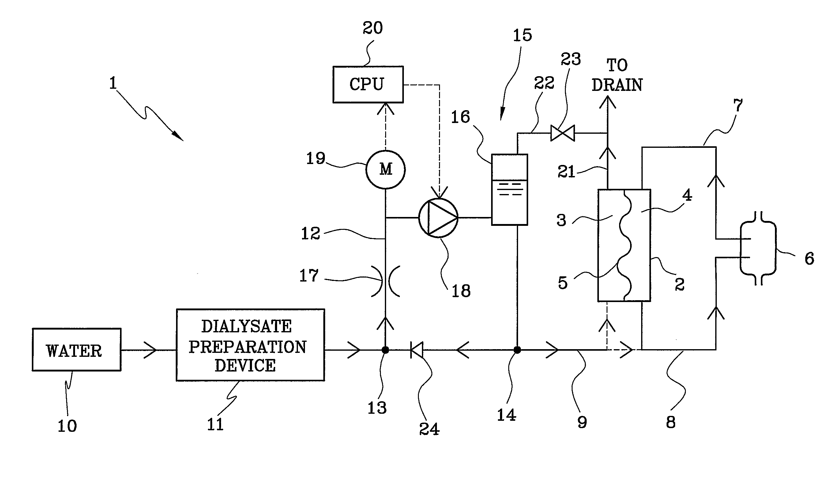
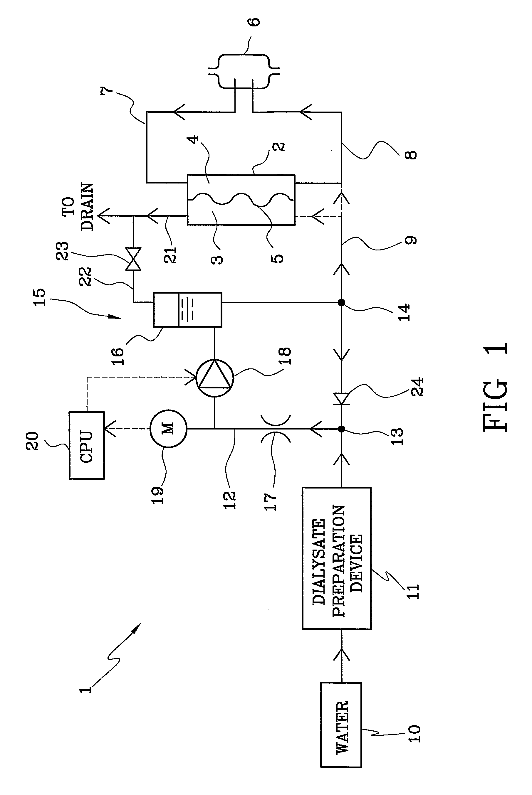
[0024]With reference to the above-cited FIG. 1 of the drawings, 1 denotes in its entirety a blood treatment apparatus, particularly a hemodialysis or hemo(dia)filtration apparatus.

[0025]The blood treatment apparatus 1 comprises a blood treatment unit (hemodialyser or hemo(dia)filter) 2 having a fluid chamber 3, a blood chamber 4, and a semipermeable membrane 5 separating the fluid chamber 3 from the blood chamber 4.

[0026]An extracorporeal blood circuit connects a patient vascular access 6 with the blood chamber 4. The extracorporeal blood circuit comprises an arterial line 7 for transporting the blood to be treated from the vascular access 6 to an inlet of the blood compartment 4, and a venous line 8 for returning the treated blood to the vascular access 6. The extracorporeal blood circuit can be any extracorporeal blood circuit used during a blood treatment in the prior art.

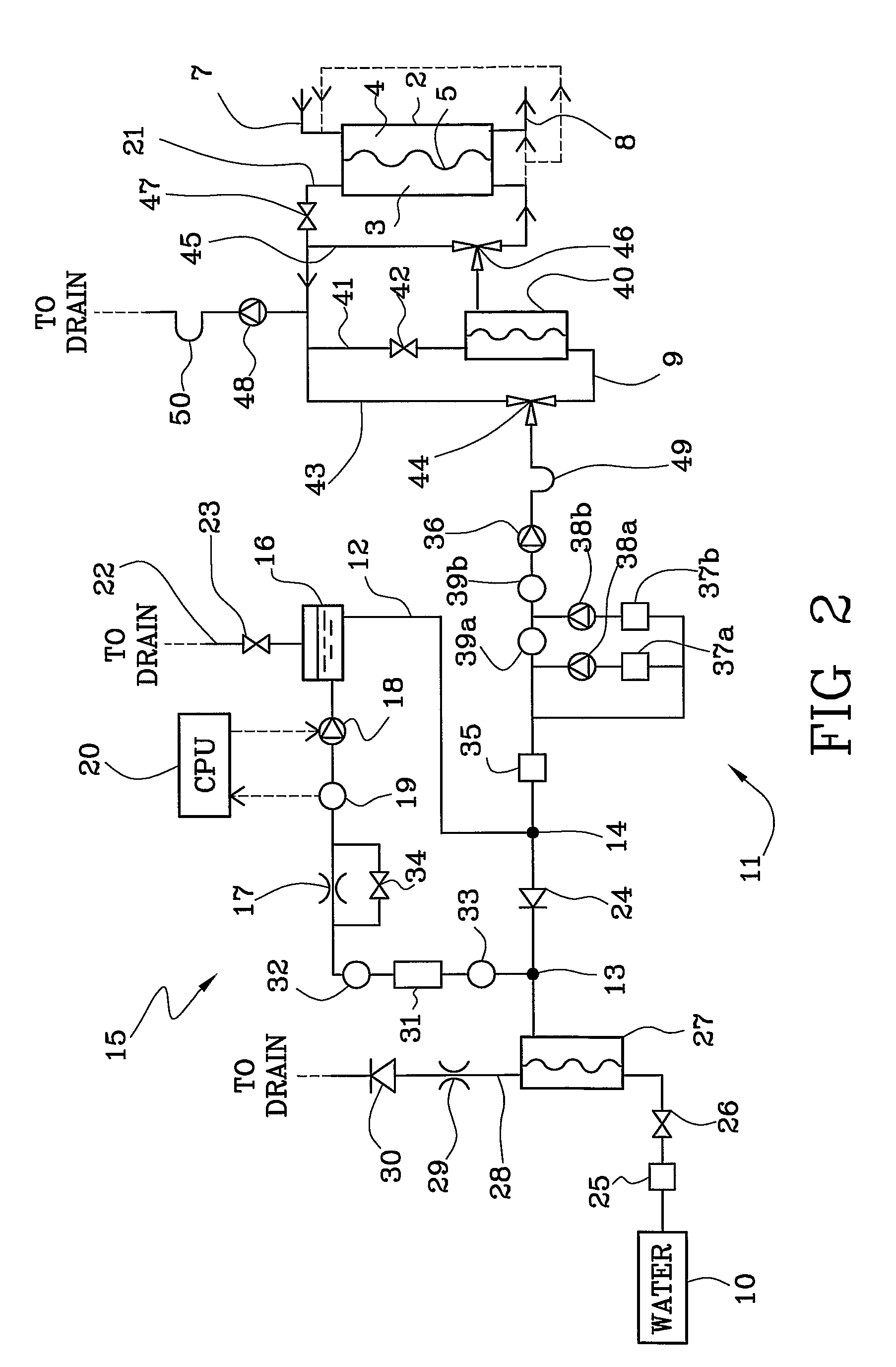
[0027]The blood treatment apparatus 1 comprises a treatment fluid supply line 9 comprising a water inlet conn...


PUM


Abstract

A blood treatment apparatus (1) comprising a degassing unit (15) receiving gas-containing fluid and supplying degassed fluid to a fluid chamber (3) of a blood treatment unit (2). The degassing unit has a gas separator (16), a degassing pump (18) to circulate fluid in a degassing line (12), a flow restrictor (17) for reducing the pressure in the degassing line (12), an absolute pressure sensor (19), and a control unit (20) designed to control the speed of said degassing pump from the absolute pressure signal emitted by the pressure sensor. The apparatus comprises a dialysis machine provided with a device for preparing on-line a dialysis liquid from water and concentrates. The apparatus achieves an accurate and reliable regulation of a desired concentration of gas in the dialysis liquid.

Description

BACKGROUND OF THE INVENTION[0001]The invention relates to a blood treatment apparatus, and particularly to a blood treatment apparatus provided with a device for on-line preparation of a treatment liquid.[0002]Specifically, though not exclusively the invention can be usefully applied in a dialysis machine provided with a device for preparing on-line a dialysis liquid from water and concentrates.[0003]As is well known, air bubbles in the dialysis liquid render inoperative the semipermeable membrane of the dialyzer. Therefore a dialysis machine normally includes a device for removing gas and minimizing gas in the dialysis liquid. For example, one type of gas removal system, as shown in U.S. Pat. No. 3,738,382, includes a heater for heating the water to a high temperature and a debubbling chamber for removing gas from the heated water at atmospheric pressure. This system does not effectively degass the water and the heating of the water causes dissolved minerals to precipitate and clog...

Claims


Application Information

Patent Timeline
Patent Type & Authority Patents(United States)
IPC IPC(8): A61M1/16
CPCA61M1/1658A61M1/166
Inventor HOVLAND, ROYWALLENBORG, ANDERS
Owner GAMBRO LUNDIA AB
Why Eureka
Try Eureka