Suspension arm unit for vehicle

a suspension arm and vehicle technology, applied in the direction of suspensions, metal-working apparatus, vehicle components, etc., can solve the problems of high production cost, high production cost, and increase in the number of processing steps

Active Publication Date: 2013-06-04
KUBOTA LTD
View PDF5 Cites 20 Cited by
  • Summary
  • Abstract
  • Description
  • Claims
  • Application Information

AI Technical Summary

Benefits of technology

[0007]In view of the above, it is desirable to provide a suspension arm unit for vehicle whose fabrication is simpler.
[0009]In the suspension arm of the present invention, the pair of the profile beams each having the U-shaped cross section are arranged in such a manner that the openings (of the U shapes) face each other, and the profile beams become gradually apart from each other from the distal end part to the base end part. With this configuration, by joining the distal end parts of the profile beams together, a suspension arm can be fabricated. Since a structure of the profile beam itself having the U-shaped cross section is simple, and the profile beam can be fabricated by a production method in three plates are welded or by bending processing on a single sheet metal using a very general mold and a simple press technique, the production cost can be effectively reduced. In addition, when a design change is required in, for example, the distance between the base end parts, it is relatively easily realized by changing an assembly angle of the pair of the profile beams. When the base end parts are processed for the purpose of easy welding of the bush or the like for swingably connecting the arms to the vehicle body, an appropriate shape can be obtained by simple processing of merely cutting out an end part of a vertical plate part of the U-shaped cross section into a shape of an arc.
[0011]With this configuration, since the plates forming the profile beams are overlapped in the vertical direction and welded, a welding operation is simpler, as compared with a method in which end faces of the pair of the profile beams are brought into contact at the same height level and welded. In addition, at a welding part, high rigidity is obtained due to the overlapped plates. Further, an overlap width in the front-rear direction between the plates can be appropriately adjusted so as to realize a desired finished size of the arm member, the arm member itself is not required to have high dimension accuracy, and consequently the cost can be reduced. Moreover, with this configuration, since an ideal weld surface (lap joint) is formed of two orthogonal faces including an upper face of a lower plate and an end face of an upper plate at a position where two plates are overlapped, a welding operation becomes very easy, and high weld strength is easily obtained. Further, in a case where two parallel plate parts of a U-shape of one of the profile beams is inserted into an opening of a U-shape of the other of the profile beams, the profile beams should have two different sizes (large and small) in the U-shape, while with the present configuration, the pair of the profile beams can be shaped to have exactly the same size.
[0012]In another preferred embodiment of the present invention, each of the profile beams is formed from a single plate by bending processing. With this configuration, as compared with a configuration in which the profile beam is obtained by a method in which three plates are welded, the profile beam can be fabricated in a shorter time, and higher reliability in strength can be obtained.
[0013]In other embodiment of the present invention, a maximum length in the front-rear direction of the distal end part of each of the profile beams has at least the front-rear length of a distal end part of the arm. With this configuration, the arm can easily exert satisfactory strength relative to a stress in the front-rear direction of the vehicle. In addition, since the overlap edge of the pair of the profile beams is not in the vicinity of a central portion in the front-rear direction but in the vicinity of the vertical plate part, strength in the vertical direction at a part unified by welding can be easily secured. Moreover, an area for attaching a lower end of damper for supporting a vehicle body weight can be easily secured in an upper face of the arm.

Problems solved by technology

Therefore, in order to manufacture these arm members, special press molds each having a special curve shape are required, leading to a problem that a production cost is likely to become high.
Therefore, special press jigs and advanced press techniques are required, leading to an increase in the number of processing steps, and again the production cost is likely to become high.

Method used


Image

  • Suspension arm unit for vehicle
  • Suspension arm unit for vehicle
  • Suspension arm unit for vehicle

Examples


Embodiment Construction

[0027]Hereinbelow, embodiments of the present invention will be described in detail with reference to the accompanying drawings.

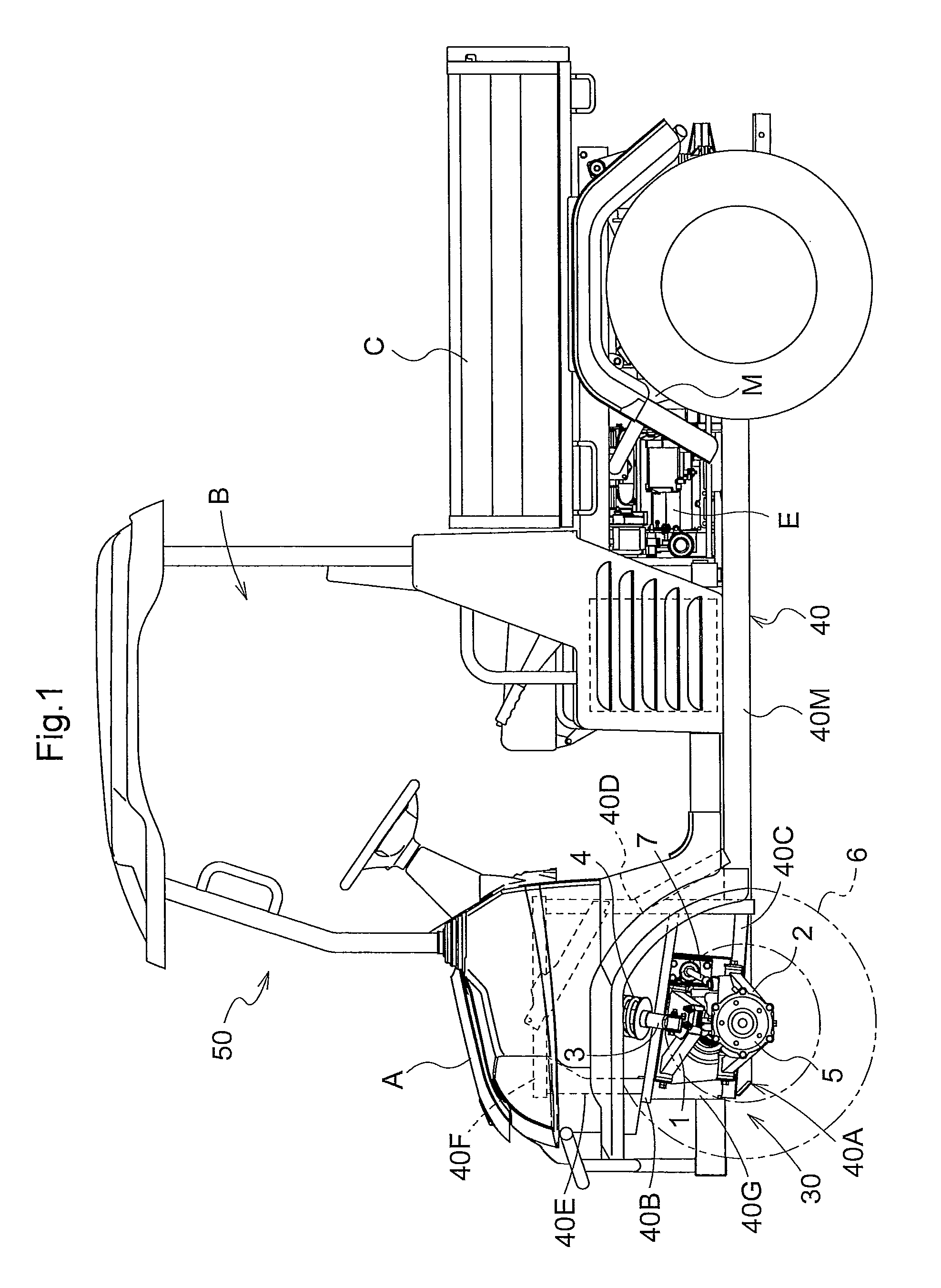
[0028]FIG. 1 shows a four-wheel drive type vehicle 50. Between steered wheels 6 as front wheels of the vehicle 50 and a body frame 40, a suspension device 30 according to the present invention is disposed. It should be noted that a basic configuration of this suspension device is also applicable to non-steered wheels.

[0029]In this embodiment, a multi-purpose work vehicle is used as the vehicle 50, which includes: a bonnet A disposed in a front part of a vehicle body; a driving part B disposed in an intermediate part of the vehicle body in a front-rear direction, between the steered wheels 6 and rear driving wheels; an engine E and a transmission case M disposed in a rear part of the vehicle body; and a truck box C disposed above the engine E and the transmission case M in the rear part of the vehicle body.

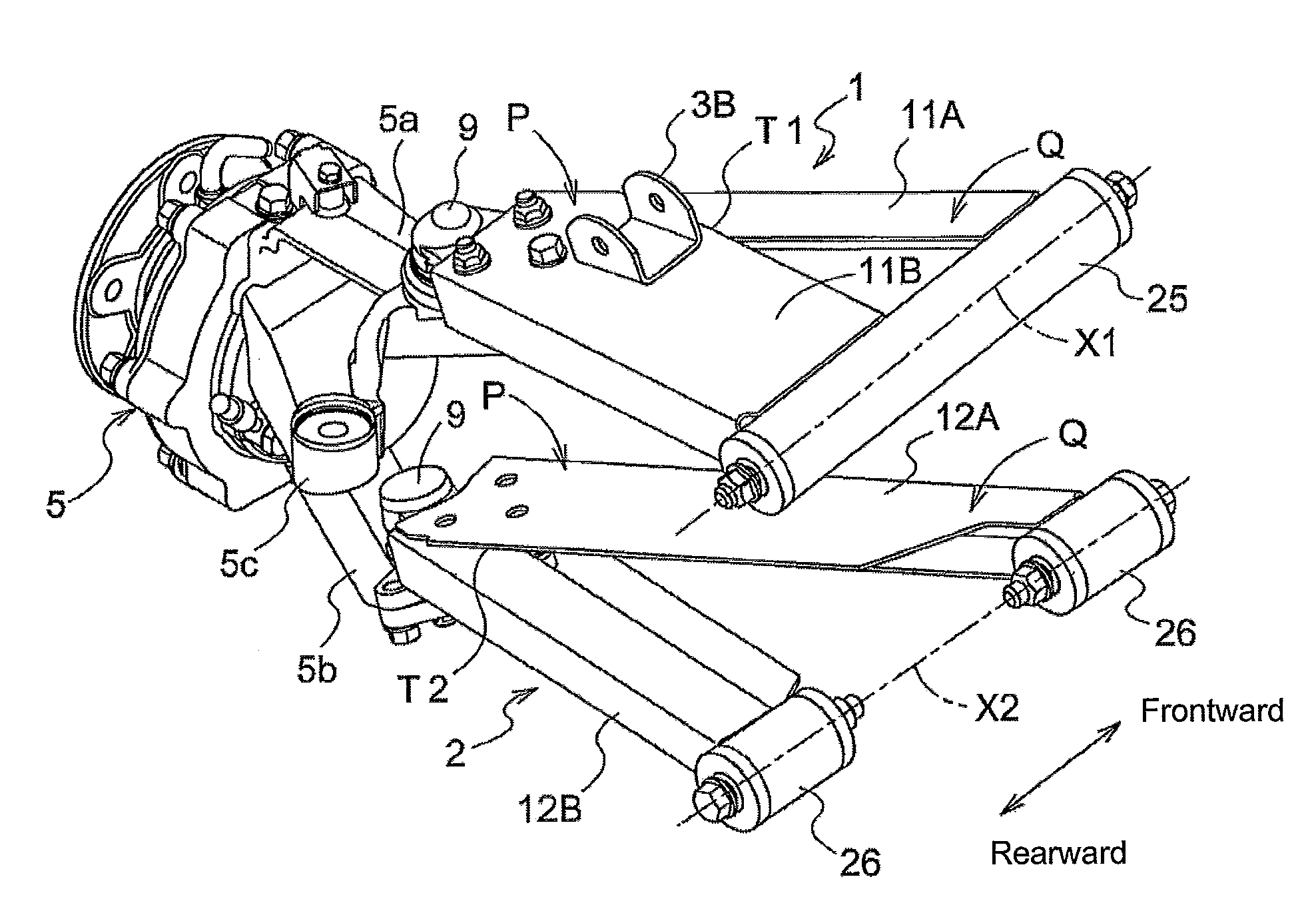
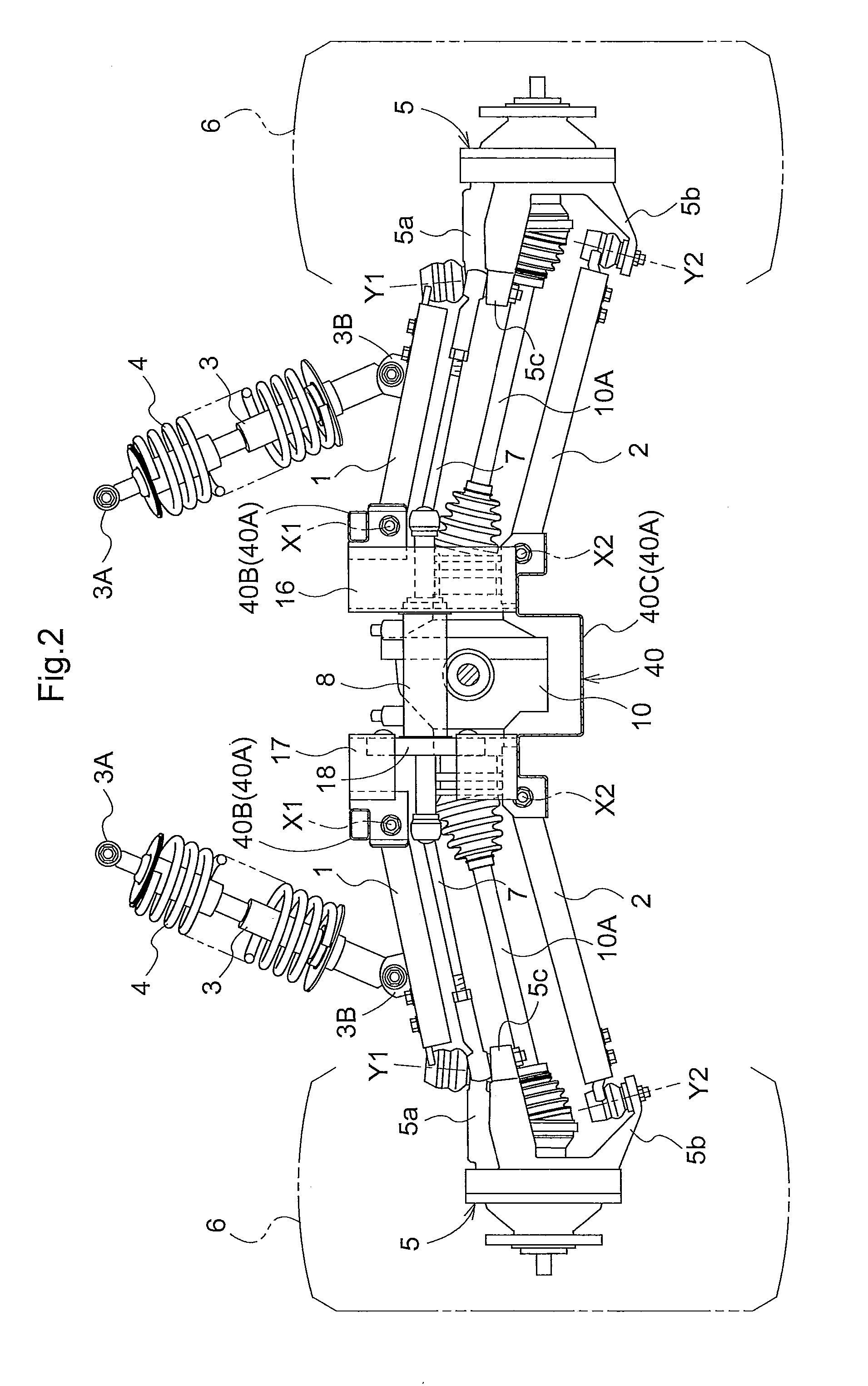
(Configuration of Suspension Device)

[0030]The suspen...


PUM

PropertyMeasurementUnit
shapesaaaaaaaaaa
structureaaaaaaaaaa
distanceaaaaaaaaaa

Abstract

A suspension arm unit for vehicle includes: a pair of profile beams each having a U-shaped cross section with an opening oriented in a horizontal direction and including: a base end part formed on one end side of the profile beam and vertically swingably supported on a vehicle body side about an axis extending in a front-rear direction; and a distal end part formed on the other end side, to which a knuckle arm unit of a wheel is attached. The pair of the profile beams are arranged in the front-rear direction so that the openings face each other in the front-rear direction and a gap between the profile beams becomes larger from the distal end part to the base end part, and the pair of the profile beams are connected to each other at the distal end part and to the knuckle arm unit through a rotary joint.

Description

BACKGROUND[0001]1. Field of the Invention[0002]The present invention relates to a suspension arm unit having: a base end part vertically swingably supported on a vehicle body side about an axis extending in a front-rear direction of a vehicle; and a distal end part to which a knuckle arm unit of a wheel is attached.[0003]2. Description of the Related Art[0004]One example of this type of suspension arm is disclosed in Japanese Unexamined Patent Application Publication No. 2001-121933 (paragraphs 0020-0023, FIG. 1). In the suspension arm described in this patent document, a pair of fork-shaped members each extending in two directions from a single distal end part to two different base end parts are butted in a vertical direction, and side faces of two members are welded together to unify two members into a single piece. Two base end parts of the thus obtained arm are apart from each other in a front-rear direction of the vehicle, and vertically swingably supported on a vehicle body si...

Claims


Application Information

Patent Timeline
Patent Type & Authority Patents(United States)
IPC IPC(8): B60G3/20B60G7/00B60G3/00
CPCB60G3/20Y10T29/49622B60G2300/13B60G2200/144
Inventor FUJII, TAKASHIKAWAMURA, SHOICHIRONISHIMURA, YUHEISAJI, SHINICHIROHAMAMURA, KYOUHEI
Owner KUBOTA LTD
Why Eureka
Try Eureka