Passive agent system impedance monitoring station and method

a passive agent and monitoring station technology, applied in the field of impedance monitoring stations, can solve the problems of difficult to determine system impedance, significant voltage drop between measurement points, and limited prior art methods

Active Publication Date: 2013-06-04
ELECTRIC POWER RES INST INC
View PDF9 Cites 2 Cited by
  • Summary
  • Abstract
  • Description
  • Claims
  • Application Information

AI Technical Summary

Benefits of technology

[0011]According to another aspect of the present invention, a method of monitoring impedance of an electrical system includes the steps of providing an impedance monitoring station having software installed thereon and adapted to test and monitor system impedance, running an initialization test using the software to compare an actual load current to reconstructed current waveforms, and taking Thevenin equivalent source measurements for voltage and current. The invention further including the steps of using Fast Fourier Transform to reduce the influence of noise and momentary changes in waveforms, analyzing data and reconstructing waveforms for voltage and current, solving for system impedance in a time domain using Least Squares, solving for a Thevenin source voltage and a Thevenin source phase angle, calculating a non-conduction voltage error to determine if a direct solution is under or over estimated, calculating harmonic impedance in a frequency domain, and determining a time domain driving point impedance and a frequency domain driving point impedance to identify the impedance of the system.

Problems solved by technology

Despite the fact that system impedance is the most important parameter in determining arc fault current that will occur when a system is short circuited, electrical one-line diagrams are often not kept up-to-date with actual system wiring, making it difficult to determine system impedance.
As a result, prior art methods encompass only limited information.
For example, one method used to measure system impedance requires the test load to be considerably large so that it creates a significant voltage drop between measurement points.
Two voltage measurements are required, but the method is unable to determine the change in voltage phase angle.
This procedure is also subject to errors caused by capacitor banks in the system such that the resistance is over-estimated.
The disadvantage of this procedure is that the solution can not be made for the driving point impedance due to the dominance of existing line voltage.
The interpolation may be linear; however, it does not always have the same curve fit.
Resonance at low frequencies will cause the system inductance to be under-estimated.
The system inductance will then be subject to erroneous results.
When the system is contaminated with voltage harmonics, the use of magnitude voltage drop will further increase error.
It is problematic that the waveforms do not align with the appropriate time stamp or phase angle when two voltage measurements are taken at different locations.

Method used


Image

  • Passive agent system impedance monitoring station and method
  • Passive agent system impedance monitoring station and method
  • Passive agent system impedance monitoring station and method

Examples


Embodiment Construction

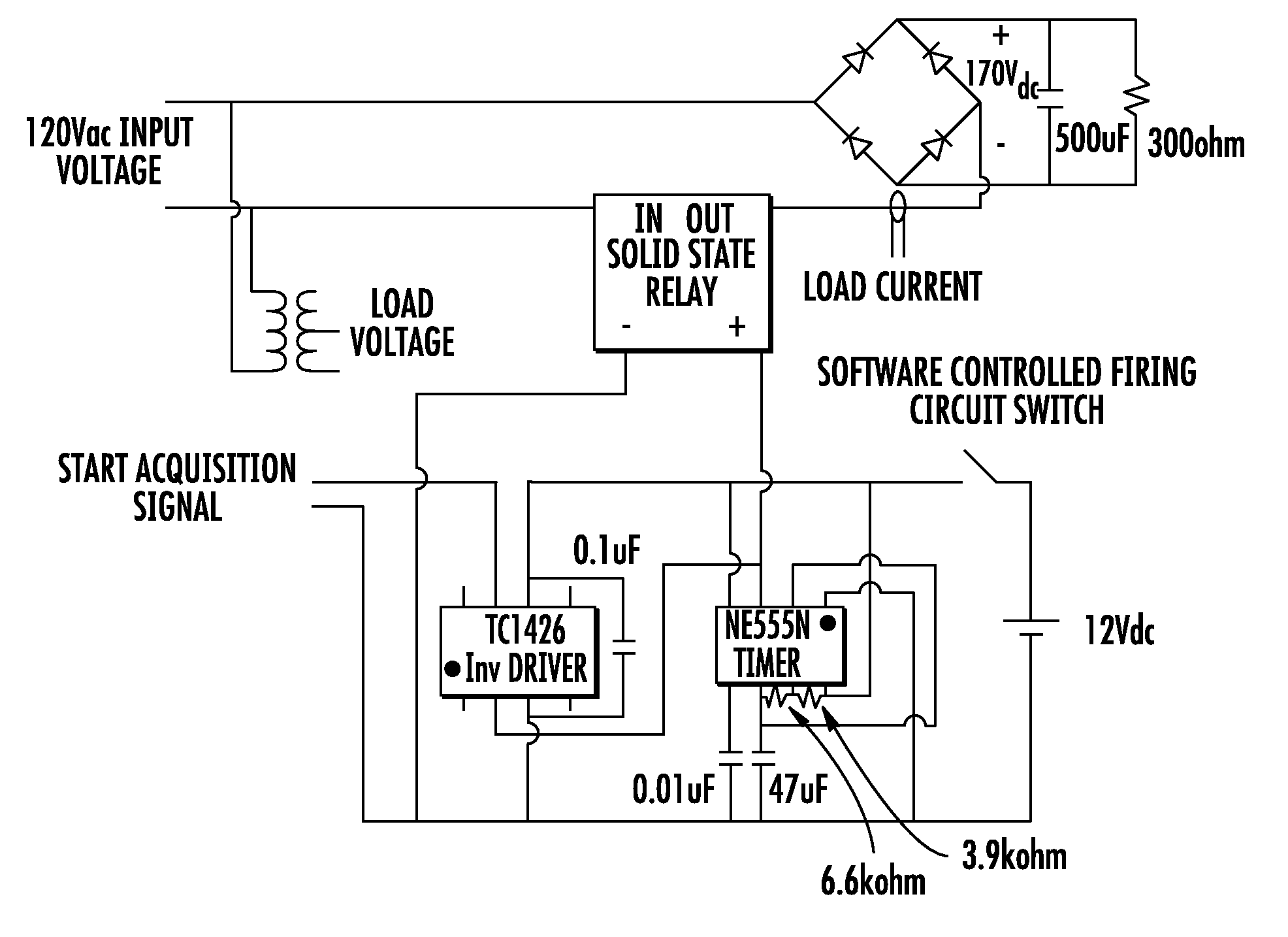
[0027]Referring to the drawings, an exemplary passive agent system impedance monitoring station (PASIMS) constructed according to the present invention is illustrated in FIG. 1. PASIMS incorporates two techniques to solve for system impedance. The first technique is to solve for system impedance in the time domain using actual system response. The second is to solve the system impedance in the frequency domain by interpolating the impedance from individual harmonic current and voltage measurements.

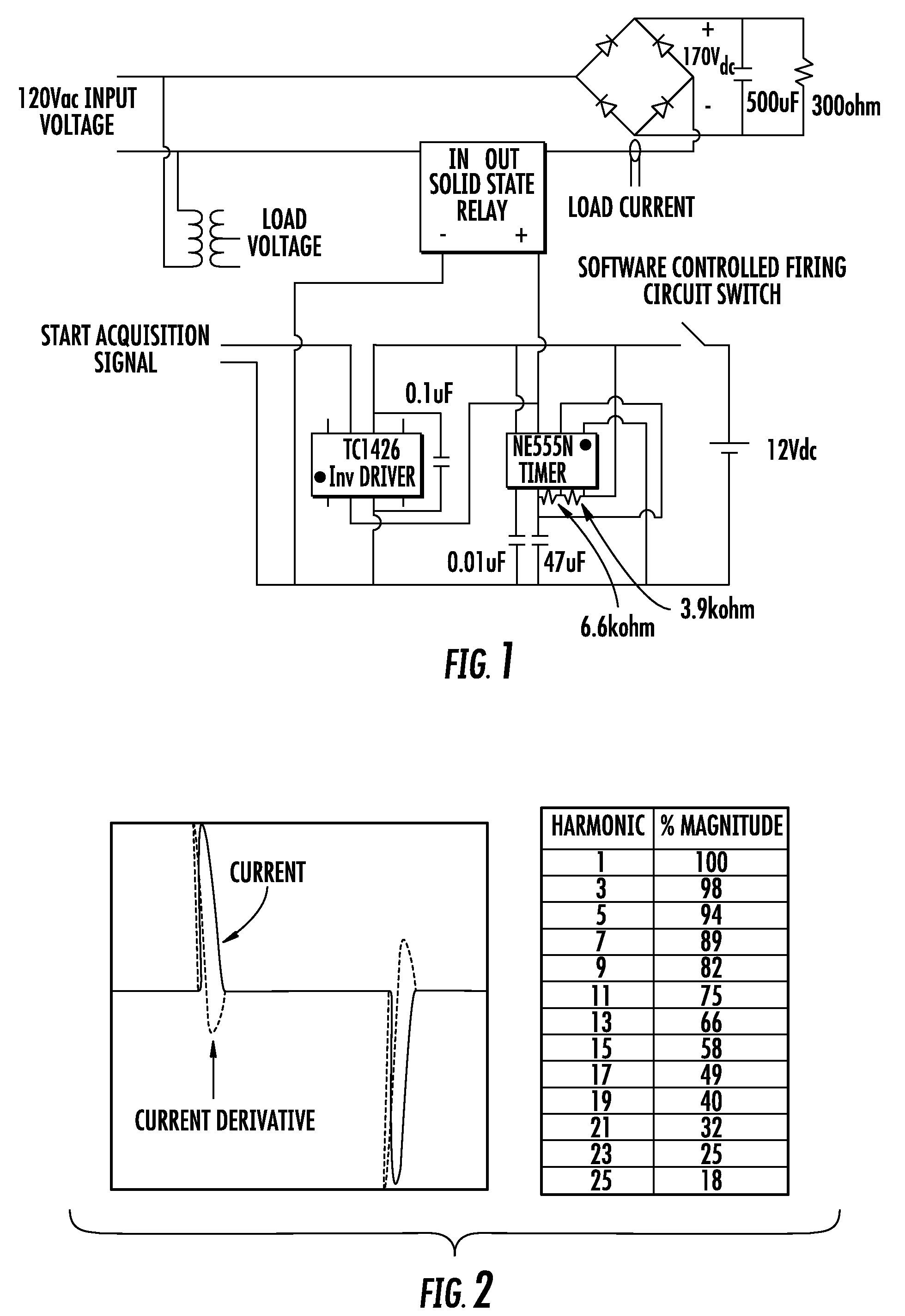
[0028]The time domain technique uses the actual time domain response of the system due to the power electronic load. This results in a dip in voltage only at the peak of the voltage waveform. This is due to the power electronic load being designed to have an approximately 5% DC voltage ripple. For PASIMS, a relatively small load (100 W on rectified 120Vac or 350 W on rectified 277Vac) causes a significant voltage dip as seen in FIG. 2.

[0029]The initial procedure for measuring system impeda...


PUM


Abstract

This invention relates to a hybrid passive agent system impedance monitoring station and method. The method of monitoring impedance of an electrical system includes the steps of providing an impedance monitoring station adapted to test and monitor system impedance, solving for system impedance in a time domain, solving for system impedance in a frequency domain, and determining a time domain driving point impedance and a frequency domain driving point impedance to identify the impedance of the system.

Description

[0001]This application claims the benefit of Provisional Application No. 61 / 103,016 filed on Oct. 6, 2008.BACKGROUND OF THE INVENTION[0002]The present invention relates generally to an impedance monitoring station, and more particularly to a hybrid passive agent system impedance monitoring station and method.[0003]System protection and personal safety is directly related to system impedance which specifies, by Ohm's law, the maximum current that can flow in a circuit. Despite the fact that system impedance is the most important parameter in determining arc fault current that will occur when a system is short circuited, electrical one-line diagrams are often not kept up-to-date with actual system wiring, making it difficult to determine system impedance.[0004]Prior art methods of determining system impedance typically involves either solving only directly or interpretively the power frequency impedance. As a result, prior art methods encompass only limited information.[0005]For examp...

Claims


Application Information

Patent Timeline
Patent Type & Authority Patents(United States)
IPC IPC(8): G01R27/04
CPCG01R27/16
Inventor RYLANDER, MATTHEW ROBERTGRADY, WILLIAM MACKMANSOOR, ARSHADGORGETTE, FREDERIC
Owner ELECTRIC POWER RES INST INC
Why Eureka
Try Eureka