Axial flow fan, in particular for a motor vehicle

a technology of axial flow fan and motor vehicle, which is applied in the direction of positive displacement liquid engine, piston pump, liquid fuel engine, etc., can solve the problems of air flow exiting the axial flow fan affected by a swirl, pressure increase through the diffuser effect, and loss through a greater throttling

Active Publication Date: 2013-06-11
BEHR GMBH & CO KG
View PDF17 Cites 5 Cited by
  • Summary
  • Abstract
  • Description
  • Claims
  • Application Information

AI Technical Summary

Benefits of technology

[0009]It is therefore an object of the present invention to improve an axial flow fan with respect to its fan capacity, in particular through the targeted influence of its outflow field, wherein at the same time a compact construction in the axial direction is to be achieved.
[0010]In an embodiment of the invention, the fan blades can form a blade overhang with respect to the shroud ring and that flow guidance elements are arranged radially outside the fan blades and in the region of the blade overhang. The blade tips of the fan blades are thus not encased by the shroud ring in their outflow-side region, the region of the blade overhang, but run freely in this region. A fan outflow directed radially already forms in the blade tip region due to the blade overhang, which fan outflow strikes the flow guidance elements arranged radially outside. The advantage is thus achieved that the flow generated by the fan in the blade tip region is delayed, that the swirl is removed from the fan outflow and converted into static pressure (pressure recovery). The energy of the swirl flow in the fan outflow field is therefore not lost.
[0011]According to an embodiment, the flow guidance elements can be essentially aligned radially, or they have a radial and tangential course. The fan outlet air can thus be guided out of the engine compartment in a manner more free of losses. The conversion of the swirl flow into static pressure is caused hereby, and the air flowing away is advantageously dissipated.

Problems solved by technology

Due to the customary compact construction in the engine compartment of the motor vehicle, these obstacles, in particular the internal combustion engine are arranged at a small axial distance behind the axial flow fan, whereby effects of a blocking can result, in particular a pressure loss through a greater throttling, but also a pressure increase through diffuser effect.
Furthermore, the air flow exiting the axial flow fan is affected by a swirl, which cannot be used for an additional pressure buildup—in fact the energy associated therewith is dissipated.
Finally, the problem of recirculation also frequently occurs, i.e., the induction again of heated air that has exited from the axial flow fan.
This leads to a deterioration of the cooling capacity.
Thus a relatively large axial construction depth proves to be a disadvantage, since the depth of the fan blades and the depth of the flow guidance elements add up in the axial direction.

Method used


Image

  • Axial flow fan, in particular for a motor vehicle
  • Axial flow fan, in particular for a motor vehicle
  • Axial flow fan, in particular for a motor vehicle

Examples


Embodiment Construction

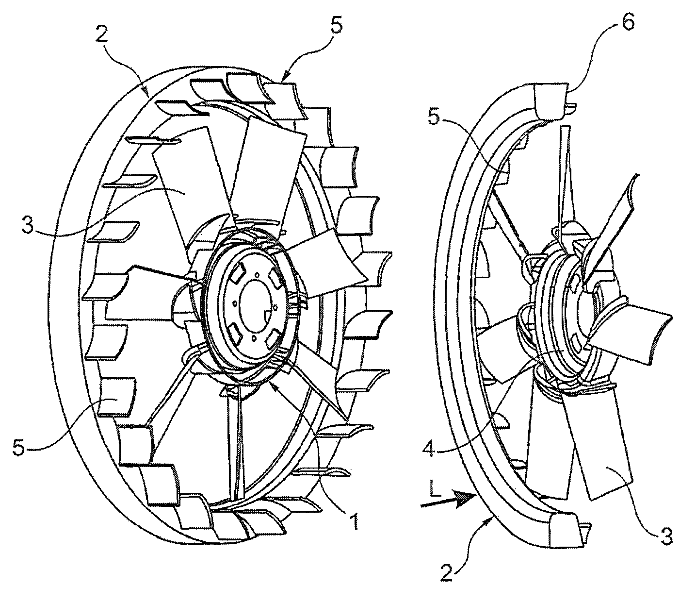
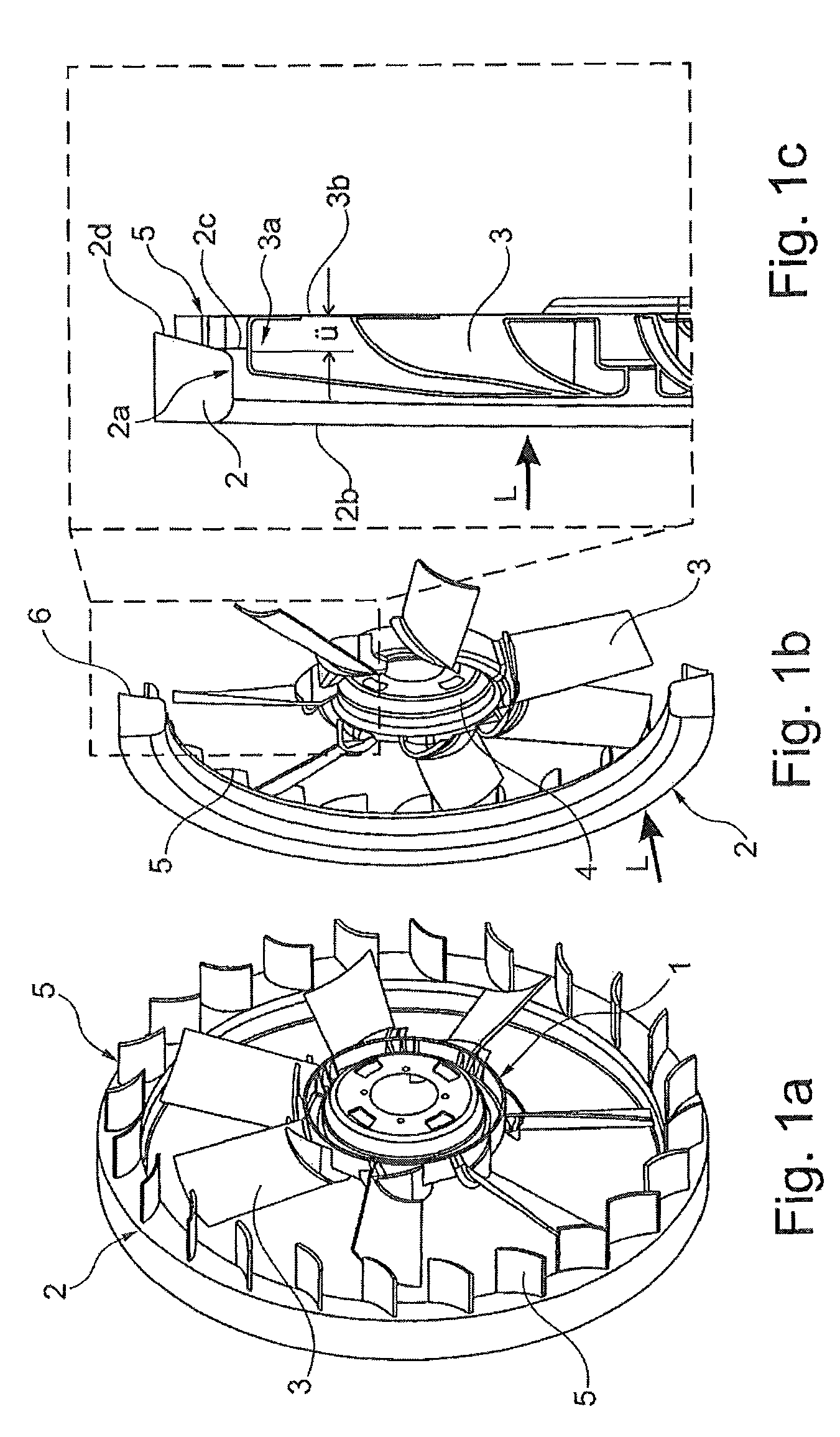
[0028]FIGS. 1a, 1b, 1c show as a first exemplary embodiment of the invention an axial flow fan 1, which is arranged in a rotatable manner in a shroud ring 2 (also referred to as a diffuser ring or casing) arranged in a stationary manner. The axial flow fan 1 comprises fan blades 3 embodied as axial vanes as well as a fan hub 4, which is connected to a fan clutch (not shown), preferably a viscous friction clutch. The axial flow fan 1, also referred to below as fan 1 for short, is attached with respect to an internal combustion engine (not shown) of a motor vehicle and is driven by the internal combustion engine, preferably directly, i.e., via a crankshaft (not shown) of the internal combustion engine. An indirect drive via an intermediate drive embodied, for example, as a variable belt drive is likewise possible. The axial flow fan 1 is thus arranged in an engine-mounted manner. The shroud ring 2 has an annular surface 2a embodied essentially in a cylindrical manner, which partially ...


PUM


Abstract

An axial flow fan is provided that is arranged in a rotatable manner around an axis in a stationary shroud ring, with fan blades. The shroud ring has an essentially cylindrical annular surface with an axial extension from a leading edge to a trailing edge and the fan blades have an axial depth from an inflow edge to an outflow edge. The outflow edges of the fan blades in an axial direction project beyond the trailing edge of the annular surface and form a blade overhang and flow guidance elements are arranged radially outside the fan blades as well as in the axial region of the blade overhang.

Description

[0001]This nonprovisional application claims priority under 35 U.S.C. §119(a) to German Patent Application No. DE 10 2009 015 104.4, which was filed in Germany on Mar. 31, 2009, and which is herein incorporated by reference.BACKGROUND OF THE INVENTION[0002]1. Field of the Invention[0003]The invention relates to an axial flow fan.[0004]2. Description of the Background Art[0005]Axial flow fans are used as blowers in motor vehicles, wherein the axial flow fan is arranged in the direction of air flow downstream of a heat exchanger or a group of heat exchangers and suctions ambient air through the heat exchanger or heat exchangers for cooling purposes. The axial flow fan runs in a shroud ring, i.e., a stationary case, wherein the shroud ring is part of a shroud or a fan cowl, which adjoins the heat exchanger or the group of heat exchangers. The internal combustion engine of the motor vehicle as well as additional units of the internal combustion engine are arranged downstream of the axia...

Claims


Application Information

Patent Timeline
Patent Type & Authority Patents(United States)
IPC IPC(8): F04D19/00
CPCF04D29/164F04D29/384F04D29/681F04D29/526F04D29/444F05D2250/52
Inventor KLEBER, ANDREAS
Owner BEHR GMBH & CO KG
Why Eureka
Try Eureka